HP Pavilion dv3-2300 HP Pavilion dv3 Entertainment PC - Maintenance and Servic - Page 102
and the two Phillips PM2.5×6.0 screws, Mylar screw covers
 |
View all HP Pavilion dv3-2300 manuals
Add to My Manuals
Save this manual to your list of manuals |
Page 102 highlights
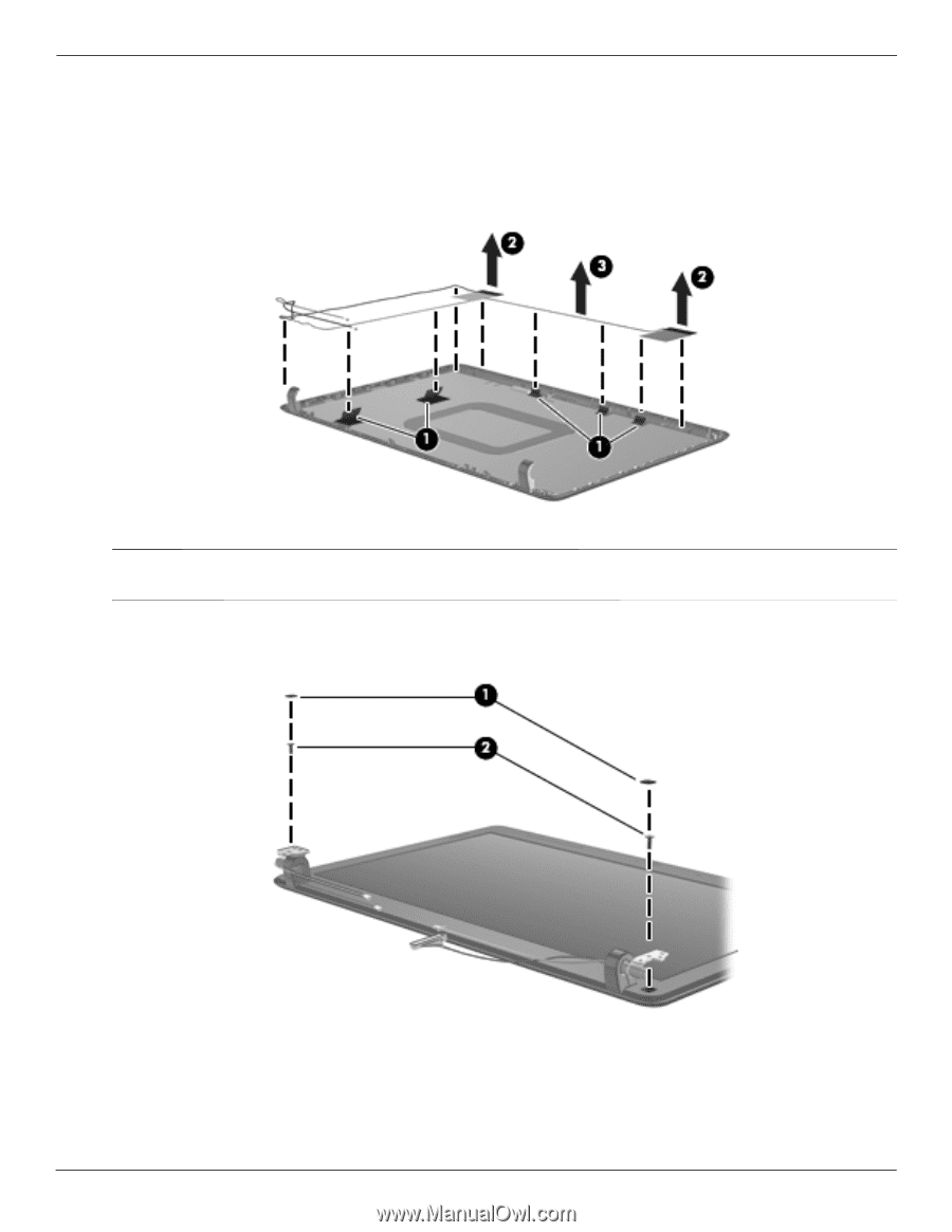
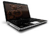
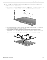
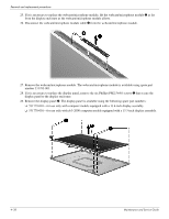
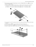
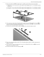
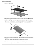
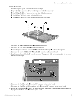
Removal and replacement procedures 36. If it is necessary to replace the wireless antenna transceivers and cables, release the tabs 1 built into the display enclosure shielding. 37. Release the wireless antenna transceivers 2 from the display enclosure. The transceivers are attached to the enclosure with double-sided tape. 38. Remove the wireless antenna transceivers and cables 3. The wireless antenna transceivers and cables are available using spare part number 531781-001. ✎ Steps 39 through 57 provide display assembly internal component removal information for computer models equipped with touch screen display assemblies. 39. If it is necessary to replace the display bezel or any of the display assembly internal components, remove the Mylar screw covers 1 and the two Phillips PM2.5×6.0 screws 2 on the display bezel lower edge. 40. Flex the inside edges of the top edge 1, the left and right sides 2, and the bottom edge of the display bezel 3 until the bezel disengages from the display enclosure. 4-40 Maintenance and Service Guide
-
 1
1 -
2
-
3
-
4
-
5
-
6
-
7
-
8
-
9
-
10
-
11
-
12
-
13
-
14
-
15
-
16
-
17
-
18
-
19
-
20
-
21
-
22
-
23
-
24
-
25
-
26
-
27
-
28
-
29
-
30
-
31
-
32
-
33
-
34
-
35
-
36
-
37
-
38
-
39
-
40
-
41
-
42
-
43
-
44
-
45
-
46
-
47
-
48
-
49
-
50
-
51
-
52
-
53
-
54
-
55
-
56
-
57
-
58
-
59
-
60
-
61
-
62
-
63
-
64
-
65
-
66
-
67
-
68
-
69
-
70
-
71
-
72
-
73
-
74
-
75
-
76
-
77
-
78
-
79
-
80
-
81
-
82
-
83
-
84
-
85
-
86
-
87
-
88
-
89
-
90
-
91
-
92
-
93
-
94
-
95
-
96
-
 97
97 -
 98
98 -
 99
99 -
 100
100 -
 101
101 -
 102
102 -
 103
103 -
 104
104 -
 105
105 -
 106
106 -
 107
107 -
108
-
109
-
110
-
111
-
112
-
113
-
114
-
115
-
116
-
117
-
118
-
119
-
120
-
121
-
122
-
123
-
124
-
125
-
126
-
127
-
128
-
129
-
130
-
131
-
132
-
133
-
134
-
135
-
136
-
137
-
138
-
139
-
140
-
141
-
142
-
143
-
144
-
145
-
146
-
147
-
148
-
149
-
150
-
151
-
152
-
153
-
154
-
155
-
156
-
157
-
158
-
159
-
160
-
161
-
162
-
163
-
164
-
165
-
166
-
167
-
168
-
169
-
170
-
171
-
172
-
173
-
174
-
175
-
176
-
177
-
178
-
179
-
180
-
181
-
182
 |
 |