HP Pavilion dv3-4300 HP Pavilion dv3 Entertainment PC - Maintenance and Servic - Page 80
Optical drive connector board
 |
View all HP Pavilion dv3-4300 manuals
Add to My Manuals
Save this manual to your list of manuals |
Page 80 highlights
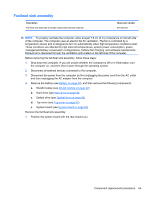
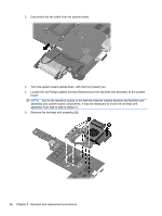
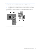
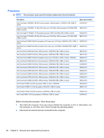
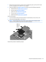
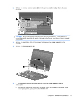
Optical drive connector board Description Optical drive connector cable Spare part number 603921-001 Before removing the optical drive connector board, follow these steps: 1. Shut down the computer. If you are unsure whether the computer is off or in Hibernation, turn the computer on, and then shut it down through the operating system. 2. Disconnect all external devices connected to the computer. 3. Disconnect the power from the computer by first unplugging the power cord from the AC outlet and then unplugging the AC adapter from the computer. 4. Remove the battery (see Battery on page 38), and then remove the following components: a. WLAN module (see WLAN module on page 42) b. Hard drive (see Hard drive on page 46 c. Optical drive (see Optical drive on page 50) d. Top cover (see Top cover on page 51) e. System board (see System board on page 62) Remove the optical drive connector board: 1. Remove the Phillips PM2.0×4.0 screw (1) that secures the optical drive connector board to the base enclosure. 2. Lift the front edge of the optical drive connector board bracket (2) until it rests at an angle. 3. Remove the optical drive connector bracket (3) by sliding it up and forward at an angle. The optical drive connector bracket is included in the Bracket Kit, spare part number 603925-001. 4. Remove the optical drive connector board (4). 70 Chapter 4 Removal and replacement procedures
-
 1
1 -
2
-
3
-
4
-
5
-
6
-
7
-
8
-
9
-
10
-
11
-
12
-
13
-
14
-
15
-
16
-
17
-
18
-
19
-
20
-
21
-
22
-
23
-
24
-
25
-
26
-
27
-
28
-
29
-
30
-
31
-
32
-
33
-
34
-
35
-
36
-
37
-
38
-
39
-
40
-
41
-
42
-
43
-
44
-
45
-
46
-
47
-
48
-
49
-
50
-
51
-
52
-
53
-
54
-
55
-
56
-
57
-
58
-
59
-
60
-
61
-
62
-
63
-
64
-
65
-
66
-
67
-
68
-
69
-
70
-
71
-
72
-
73
-
74
-
 75
75 -
 76
76 -
 77
77 -
 78
78 -
 79
79 -
 80
80 -
 81
81 -
 82
82 -
 83
83 -
 84
84 -
 85
85 -
86
-
87
-
88
-
89
-
90
-
91
-
92
-
93
-
94
-
95
-
96
-
97
-
98
-
99
-
100
-
101
-
102
-
103
-
104
-
105
-
106
-
107
-
108
-
109
-
110
-
111
-
112
-
113
-
114
-
115
-
116
 |
 |
