HP Pavilion dv5-1100 HP Pavilion dv5 Entertainment PC - Maintenance and Servic - Page 108
that service, and the s of the heat sink
 |
View all HP Pavilion dv5-1100 manuals
Add to My Manuals
Save this manual to your list of manuals |
Page 108 highlights
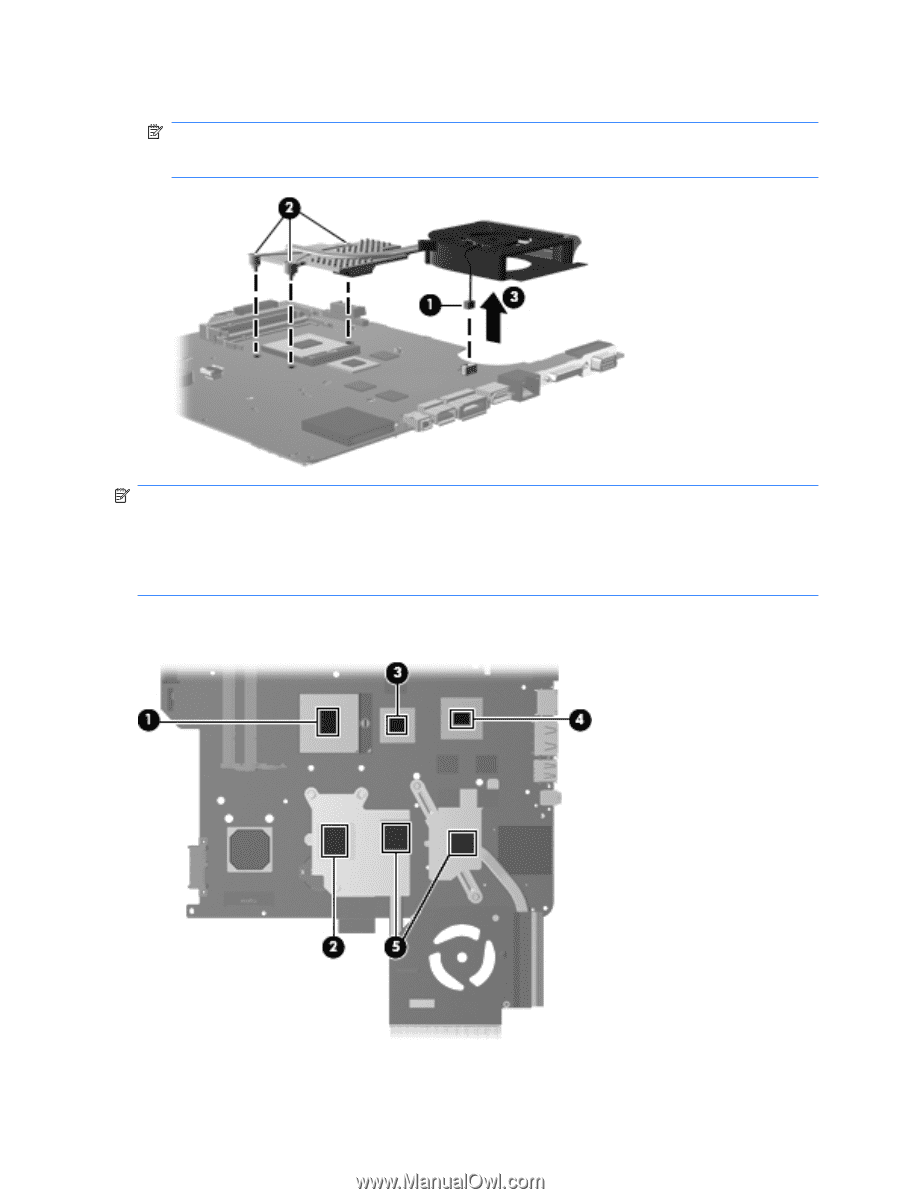
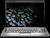
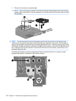
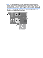
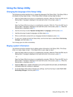
7. Remove the fan/heat sink assembly (3). NOTE: Due to the adhesive quality of the thermal material located between the heat sink and system board components, it may be necessary to move the heat sink from side to side to detach the assembly. NOTE: The thermal material must be thoroughly cleaned from the surfaces of the fan/heat sink assembly and the system board each time the fan/heat sink assembly is removed. Thermal paste is used on the processor (1) and the heat sink section (2) that services it. Thermal pads are used on the Northbridge chip (3), the graphics subsystem chip (4), and the sections of the heat sink (5) that service them. Replacement thermal material is included with all fan/heat sink assembly, system board, and processor spare part kits. The following illustration shows the replacement thermal material locations for computer models equipped with graphics subsystems with discrete memory. 100 Chapter 4 Removal and replacement procedures
-
 1
1 -
2
-
3
-
4
-
5
-
6
-
7
-
8
-
9
-
10
-
11
-
12
-
13
-
14
-
15
-
16
-
17
-
18
-
19
-
20
-
21
-
22
-
23
-
24
-
25
-
26
-
27
-
28
-
29
-
30
-
31
-
32
-
33
-
34
-
35
-
36
-
37
-
38
-
39
-
40
-
41
-
42
-
43
-
44
-
45
-
46
-
47
-
48
-
49
-
50
-
51
-
52
-
53
-
54
-
55
-
56
-
57
-
58
-
59
-
60
-
61
-
62
-
63
-
64
-
65
-
66
-
67
-
68
-
69
-
70
-
71
-
72
-
73
-
74
-
75
-
76
-
77
-
78
-
79
-
80
-
81
-
82
-
83
-
84
-
85
-
86
-
87
-
88
-
89
-
90
-
91
-
92
-
93
-
94
-
95
-
96
-
97
-
98
-
99
-
100
-
101
-
102
-
 103
103 -
 104
104 -
 105
105 -
 106
106 -
 107
107 -
 108
108 -
 109
109 -
 110
110 -
 111
111 -
 112
112 -
 113
113 -
114
-
115
-
116
-
117
-
118
-
119
-
120
-
121
-
122
-
123
-
124
-
125
-
126
-
127
-
128
-
129
-
130
-
131
-
132
-
133
-
134
-
135
-
136
-
137
-
138
-
139
-
140
-
141
-
142
-
143
-
144
-
145
-
146
-
147
-
148
-
149
-
150
-
151
-
152
-
153
-
154
-
155
-
156
-
157
-
158
-
159
-
160
-
161
-
162
-
163
-
164
-
165
-
166
-
167
-
168
-
169
-
170
-
171
-
172
-
173
 |
 |