HP Pavilion dv5000 HP Pavilion dv5000 Notebook PC - Maintenance and Service Gu - Page 89
Description, of Screws Removed
 |
View all HP Pavilion dv5000 manuals
Add to My Manuals
Save this manual to your list of manuals |
Page 89 highlights
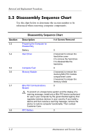
Removal and Replacement Procedures Disassembly Sequence Chart (Continued) Section 5.9 Description Optical Drive 5.10 Switch Cover 5.11 Keyboard Frame 5.12 LED Board 5.13 Keyboard 5.14 Display Assembly 5.15 Top Cover 5.16 Bluetooth Module 5.17 System Board 5.18 USB/Audio Board 5.19 Heat Sink 5.20 Processor 5.21 Fan Assembly 5.22 Speakers 5.23 PC Card Assembly 5.24 ExpressCard Assembly # of Screws Removed 1 to remove to optical drive 2 to remove the optical drive bracket 7 1 5 4 4 to remove the display assembly 8 to remove the display bezel 2 to remove the display panel 4 to remove each display hinge 1 to remove each wireless antenna transceiver 21 1 6 1 4 1 loosened on select models 5 1 2 2 Maintenance and Service Guide 5-3
-
 1
1 -
2
-
3
-
4
-
5
-
6
-
7
-
8
-
9
-
10
-
11
-
12
-
13
-
14
-
15
-
16
-
17
-
18
-
19
-
20
-
21
-
22
-
23
-
24
-
25
-
26
-
27
-
28
-
29
-
30
-
31
-
32
-
33
-
34
-
35
-
36
-
37
-
38
-
39
-
40
-
41
-
42
-
43
-
44
-
45
-
46
-
47
-
48
-
49
-
50
-
51
-
52
-
53
-
54
-
55
-
56
-
57
-
58
-
59
-
60
-
61
-
62
-
63
-
64
-
65
-
66
-
67
-
68
-
69
-
70
-
71
-
72
-
73
-
74
-
75
-
76
-
77
-
78
-
79
-
80
-
81
-
82
-
83
-
 84
84 -
 85
85 -
 86
86 -
 87
87 -
 88
88 -
 89
89 -
 90
90 -
 91
91 -
 92
92 -
 93
93 -
 94
94 -
95
-
96
-
97
-
98
-
99
-
100
-
101
-
102
-
103
-
104
-
105
-
106
-
107
-
108
-
109
-
110
-
111
-
112
-
113
-
114
-
115
-
116
-
117
-
118
-
119
-
120
-
121
-
122
-
123
-
124
-
125
-
126
-
127
-
128
-
129
-
130
-
131
-
132
-
133
-
134
-
135
-
136
-
137
-
138
-
139
-
140
-
141
-
142
-
143
-
144
-
145
-
146
-
147
-
148
-
149
-
150
-
151
-
152
-
153
-
154
-
155
-
156
-
157
-
158
-
159
-
160
-
161
-
162
-
163
-
164
-
165
-
166
-
167
-
168
-
169
-
170
-
171
-
172
-
173
-
174
-
175
-
176
-
177
-
178
-
179
-
180
-
181
-
182
-
183
-
184
-
185
-
186
-
187
-
188
-
189
-
190
-
191
-
192
-
193
-
194
-
195
-
196
-
197
-
198
-
199
-
200
-
201
-
202
-
203
-
204
-
205
-
206
-
207
-
208
-
209
-
210
-
211
-
212
-
213
-
214
-
215
-
216
-
217
-
218
-
219
-
220
-
221
-
222
-
223
-
224
-
225
-
226
-
227
-
228
-
229
-
230
-
231
-
232
-
233
-
234
-
235
-
236
-
237
-
238
-
239
-
240
-
241
-
242
-
243
-
244
-
245
-
246
-
247
-
248
-
249
-
250
-
251
-
252
-
253
-
254
-
255
-
256
-
257
-
258
 |
 |
Removal and Replacement Procedures
Maintenance and Service Guide
5–3
Section
Description
# of Screws Removed
5.9
Optical Drive
1 to remove to optical drive
2 to remove the optical drive
bracket
5.10
Switch Cover
7
5.11
Keyboard Frame
1
5.12
LED Board
5
5.13
Keyboard
4
5.14
Display Assembly
4 to remove the display
assembly
8 to remove the display bezel
2 to remove the display panel
4 to remove each display
hinge
1 to remove each wireless
antenna transceiver
5.15
Top Cover
21
5.16
Bluetooth Module
1
5.17
System Board
6
5.18
USB/Audio Board
1
5.19
Heat Sink
4
5.20
Processor
1 loosened on select models
5.21
Fan Assembly
5
5.22
Speakers
1
5.23
PC Card Assembly
2
5.24
ExpressCard Assembly
2
Disassembly Sequence Chart
(Continued)