HP Pavilion dv5200 HP Pavilion dv5100 Notebook PC - Maintenance and Service Gu - Page 152
Fan/Heat Sink Assembly, Fan/Heat Sink Assembly Spare Part Number Information
 |
View all HP Pavilion dv5200 manuals
Add to My Manuals
Save this manual to your list of manuals |
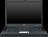
Page 152 highlights
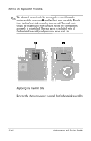
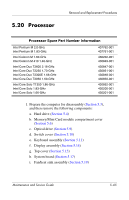
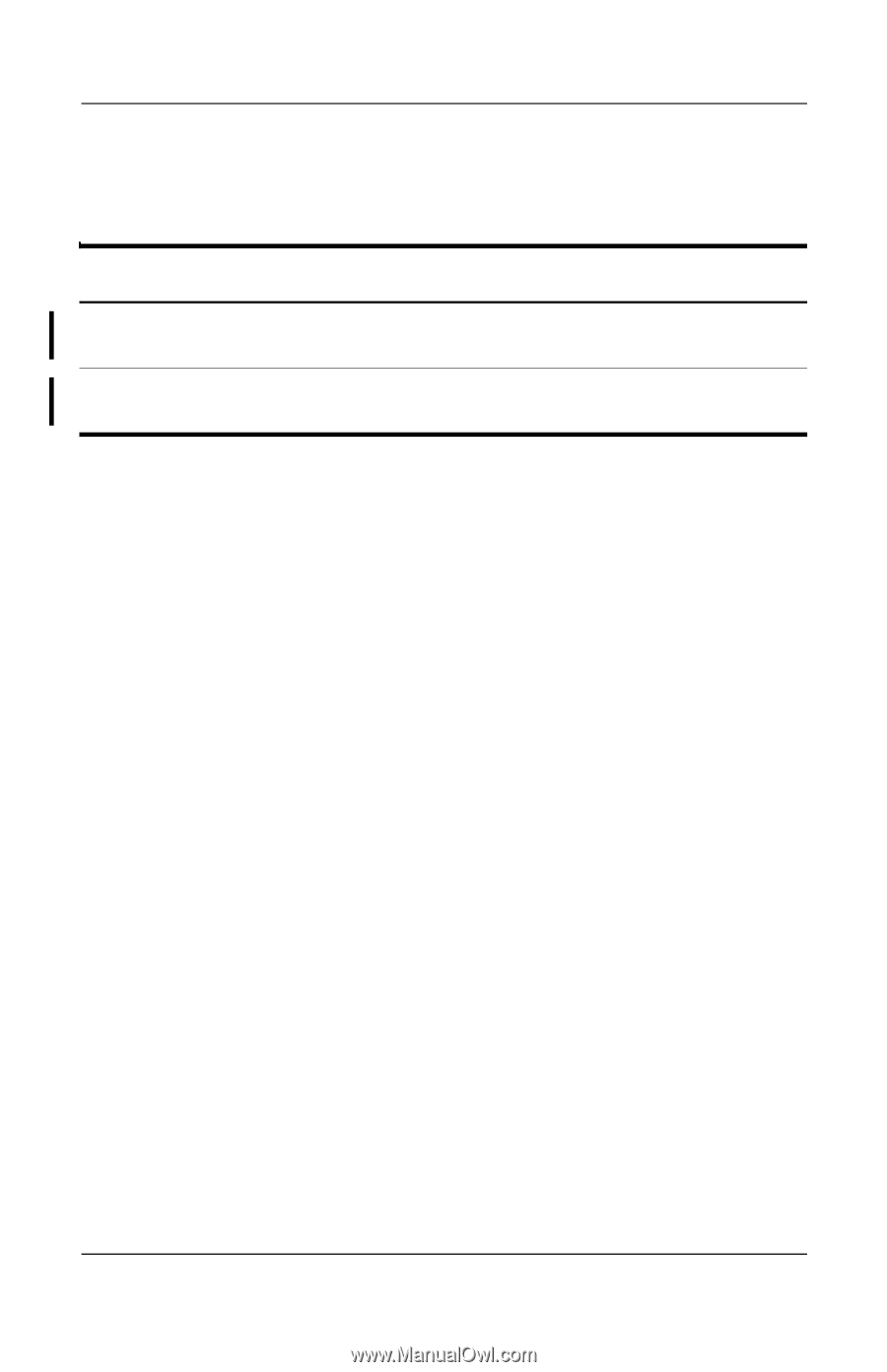
Removal and Replacement Procedures 5.19 Fan/Heat Sink Assembly Fan/Heat Sink Assembly Spare Part Number Information For use with UMA system boards For use with discrete system boards Heat sink Fan assembly 413453-001 407862-001 403827-001 407862-001 1. Prepare the computer for disassembly (Section 5.3), and then remove the following components: a. Hard drive (Section 5.4) b. Memory/Mini Card module compartment cover (Section 5.6) c. Optical drive (Section 5.9) d. Switch cover (Section 5.10) e. Keyboard assembly (Section 5.11) f. Display assembly (Section 5.14) g. Top cover (Section 5.15) h. System board (Section 5.17) 5-60 Maintenance and Service Guide
-
 1
1 -
2
-
3
-
4
-
5
-
6
-
7
-
8
-
9
-
10
-
11
-
12
-
13
-
14
-
15
-
16
-
17
-
18
-
19
-
20
-
21
-
22
-
23
-
24
-
25
-
26
-
27
-
28
-
29
-
30
-
31
-
32
-
33
-
34
-
35
-
36
-
37
-
38
-
39
-
40
-
41
-
42
-
43
-
44
-
45
-
46
-
47
-
48
-
49
-
50
-
51
-
52
-
53
-
54
-
55
-
56
-
57
-
58
-
59
-
60
-
61
-
62
-
63
-
64
-
65
-
66
-
67
-
68
-
69
-
70
-
71
-
72
-
73
-
74
-
75
-
76
-
77
-
78
-
79
-
80
-
81
-
82
-
83
-
84
-
85
-
86
-
87
-
88
-
89
-
90
-
91
-
92
-
93
-
94
-
95
-
96
-
97
-
98
-
99
-
100
-
101
-
102
-
103
-
104
-
105
-
106
-
107
-
108
-
109
-
110
-
111
-
112
-
113
-
114
-
115
-
116
-
117
-
118
-
119
-
120
-
121
-
122
-
123
-
124
-
125
-
126
-
127
-
128
-
129
-
130
-
131
-
132
-
133
-
134
-
135
-
136
-
137
-
138
-
139
-
140
-
141
-
142
-
143
-
144
-
145
-
146
-
 147
147 -
 148
148 -
 149
149 -
 150
150 -
 151
151 -
 152
152 -
 153
153 -
 154
154 -
 155
155 -
 156
156 -
 157
157 -
158
-
159
-
160
-
161
-
162
-
163
-
164
-
165
-
166
-
167
-
168
-
169
-
170
-
171
-
172
-
173
-
174
-
175
-
176
-
177
-
178
-
179
-
180
-
181
-
182
-
183
-
184
-
185
-
186
-
187
-
188
-
189
-
190
-
191
-
192
-
193
-
194
-
195
-
196
-
197
-
198
-
199
-
200
-
201
-
202
-
203
-
204
-
205
-
206
-
207
-
208
-
209
-
210
-
211
-
212
-
213
-
214
-
215
-
216
-
217
-
218
-
219
-
220
-
221
-
222
-
223
-
224
-
225
-
226
-
227
-
228
-
229
-
230
-
231
-
232
-
233
-
234
-
235
-
236
-
237
-
238
-
239
-
240
-
241
-
242
-
243
-
244
-
245
-
246
-
247
-
248
-
249
-
250
-
251
-
252
-
253
-
254
-
255
-
256
-
257
-
258
-
259
-
260
 |
 |
5–60
Maintenance and Service Guide
Removal and Replacement Procedures
5.19
Fan/Heat Sink Assembly
1. Prepare the computer for disassembly (
Section 5.3
),
and then remove the following components:
a.
Hard drive (
Section 5.4
)
b.
Memory/Mini Card module compartment cover
(
Section 5.6
)
c.
Optical drive (
Section 5.9
)
d.
Switch cover (
Section 5.10
)
e.
Keyboard assembly (
Section 5.11
)
f.
Display assembly (
Section 5.14
)
g.
Top cover (
Section 5.15
)
h.
System board (
Section 5.17
)
Fan/Heat Sink Assembly Spare Part Number Information
For use with UMA system boards
For use with discrete system boards
413453-001
407862-001
Heat sink
Fan assembly
403827-001
407862-001