HP Pavilion dv8100 HP Pavilion dv8200 Notebook PC, HP Pavilion dv8000 Notebook - Page 150
Modem Connector Cable
 |
View all HP Pavilion dv8100 manuals
Add to My Manuals
Save this manual to your list of manuals |
Page 150 highlights
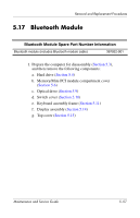
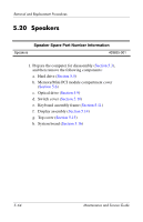
Removal and Replacement Procedures 5.18 Modem Connector Cable ✎ The modem connector cable is included in the Cable Kit, spare part number 403814-001. 1. Prepare the computer for disassembly (Section 5.3), and then remove the following components: a. Hard drive (Section 5.4) b. Memory/Mini PCI module compartment cover (Section 5.6) c. Optical drive (Section 5.9) d. Switch cover (Section 5.10) e. Keyboard assembly frame (Section 5.11) f. Display assembly (Section 5.14) g. Top cover (Section 5.15) 5-60 Maintenance and Service Guide
-
 1
1 -
2
-
3
-
4
-
5
-
6
-
7
-
8
-
9
-
10
-
11
-
12
-
13
-
14
-
15
-
16
-
17
-
18
-
19
-
20
-
21
-
22
-
23
-
24
-
25
-
26
-
27
-
28
-
29
-
30
-
31
-
32
-
33
-
34
-
35
-
36
-
37
-
38
-
39
-
40
-
41
-
42
-
43
-
44
-
45
-
46
-
47
-
48
-
49
-
50
-
51
-
52
-
53
-
54
-
55
-
56
-
57
-
58
-
59
-
60
-
61
-
62
-
63
-
64
-
65
-
66
-
67
-
68
-
69
-
70
-
71
-
72
-
73
-
74
-
75
-
76
-
77
-
78
-
79
-
80
-
81
-
82
-
83
-
84
-
85
-
86
-
87
-
88
-
89
-
90
-
91
-
92
-
93
-
94
-
95
-
96
-
97
-
98
-
99
-
100
-
101
-
102
-
103
-
104
-
105
-
106
-
107
-
108
-
109
-
110
-
111
-
112
-
113
-
114
-
115
-
116
-
117
-
118
-
119
-
120
-
121
-
122
-
123
-
124
-
125
-
126
-
127
-
128
-
129
-
130
-
131
-
132
-
133
-
134
-
135
-
136
-
137
-
138
-
139
-
140
-
141
-
142
-
143
-
144
-
 145
145 -
 146
146 -
 147
147 -
 148
148 -
 149
149 -
 150
150 -
 151
151 -
 152
152 -
 153
153 -
 154
154 -
 155
155 -
156
-
157
-
158
-
159
-
160
-
161
-
162
-
163
-
164
-
165
-
166
-
167
-
168
-
169
-
170
-
171
-
172
-
173
-
174
-
175
-
176
-
177
-
178
-
179
-
180
-
181
-
182
-
183
-
184
-
185
-
186
-
187
-
188
-
189
-
190
-
191
-
192
-
193
-
194
-
195
-
196
-
197
-
198
-
199
-
200
-
201
-
202
-
203
-
204
-
205
-
206
-
207
-
208
-
209
-
210
-
211
-
212
-
213
-
214
-
215
-
216
-
217
-
218
-
219
-
220
-
221
-
222
-
223
-
224
-
225
-
226
-
227
-
228
-
229
-
230
-
231
-
232
-
233
-
234
-
235
-
236
-
237
-
238
-
239
-
240
-
241
-
242
-
243
-
244
-
245
-
246
-
247
-
248
-
249
-
250
-
251
-
252
-
253
-
254
-
255
-
256
-
257
-
258
-
259
-
260
-
261
-
262
-
263
-
264
 |
 |

5–60
Maintenance and Service Guide
Removal and Replacement Procedures
5.18
Modem Connector Cable
✎
The modem connector cable is included in the Cable Kit, spare
part number 403814-001.
1. Prepare the computer for disassembly (
Section 5.3
),
and then remove the following components:
a.
Hard drive (
Section 5.4
)
b.
Memory/Mini PCI module compartment cover
(
Section 5.6
)
c.
Optical drive (
Section 5.9
)
d.
Switch cover (
Section 5.10
)
e.
Keyboard assembly frame (
Section 5.11
)
f.
Display assembly (
Section 5.14
)
g.
Top cover (
Section 5.15
)