HP Pavilion g4-2000 HP Pavilion g4 Notebook PC - Maintenance and Service Guide - Page 63
CAUTION, that secure the display assembly
 |
View all HP Pavilion g4-2000 manuals
Add to My Manuals
Save this manual to your list of manuals |
Page 63 highlights
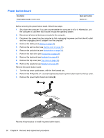
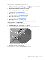
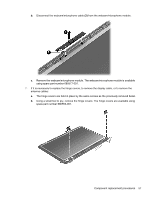
2. Release the wireless antenna cables (2) from the clips and the opening in the base enclosure. NOTE: It may be necessary to release the USB board ZIF cable to remove the wireless antenna cables. CAUTION: Support the display assembly when removing the following screws. Failure to support the display assembly can result in damage to the display assembly and other computer components. 3. Remove the four Phillips M2.5 × 6.5 screws (1) that secure the display assembly to the computer. 4. Remove the display assembly by lifting straight up (2). Component replacement procedures 55
-
 1
1 -
2
-
3
-
4
-
5
-
6
-
7
-
8
-
9
-
10
-
11
-
12
-
13
-
14
-
15
-
16
-
17
-
18
-
19
-
20
-
21
-
22
-
23
-
24
-
25
-
26
-
27
-
28
-
29
-
30
-
31
-
32
-
33
-
34
-
35
-
36
-
37
-
38
-
39
-
40
-
41
-
42
-
43
-
44
-
45
-
46
-
47
-
48
-
49
-
50
-
51
-
52
-
53
-
54
-
55
-
56
-
57
-
 58
58 -
 59
59 -
 60
60 -
 61
61 -
 62
62 -
 63
63 -
 64
64 -
 65
65 -
 66
66 -
 67
67 -
 68
68 -
69
-
70
-
71
-
72
-
73
-
74
-
75
-
76
-
77
-
78
-
79
-
80
-
81
-
82
-
83
-
84
-
85
-
86
-
87
-
88
-
89
-
90
-
91
-
92
-
93
-
94
-
95
-
96
-
97
-
98
-
99
-
100
-
101
-
102
-
103
-
104
 |
 |

2.
Release the wireless antenna cables
(2)
from the clips and the opening in the base enclosure.
NOTE:
It may be necessary to release the USB board ZIF cable to remove the wireless
antenna cables.
CAUTION:
Support the display assembly when removing the following screws. Failure to
support the display assembly can result in damage to the display assembly and other
computer components.
3.
Remove the four Phillips M2.5 × 6.5 screws
(1)
that secure the display assembly to
the computer.
4.
Remove the display assembly by lifting straight up
(2)
.
Component replacement procedures
55