HP Pavilion g6-1a00 HP G62 Notebook PC - Maintenance and Service Guide - Page 61
Power button board, Turn the top cover upside down with the rear edge toward you.
 |
View all HP Pavilion g6-1a00 manuals
Add to My Manuals
Save this manual to your list of manuals |
Page 61 highlights
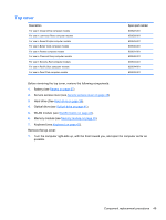
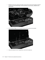
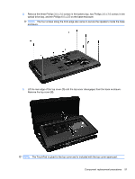
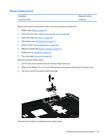
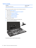
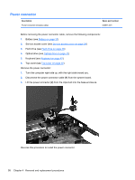
Power button board Description Power button board Spare part number 640884-001 Before removing the power button board, remove the following components: 1. Battery (see Battery on page 37) 2. Service access cover (see Service access cover on page 38) 3. Hard drive (See Hard drive on page 39) 4. Optical drive (see Optical drive on page 41) 5. WLAN module (see WLAN module on page 43). 6. Memory module (see Memory module on page 45) 7. Keyboard (see Keyboard on page 47) 8. Top cover (see Top cover on page 49) Remove the power button board: 1. Turn the top cover upside down with the rear edge toward you. 2. Remove the Phillips 3.0 x 2.0 screw (1) that secures the power button board to the top cover. 3. Lift up and remove the power button board (2). Reverse this procedure to install the power button board. Component replacement procedures 53
-
 1
1 -
2
-
3
-
4
-
5
-
6
-
7
-
8
-
9
-
10
-
11
-
12
-
13
-
14
-
15
-
16
-
17
-
18
-
19
-
20
-
21
-
22
-
23
-
24
-
25
-
26
-
27
-
28
-
29
-
30
-
31
-
32
-
33
-
34
-
35
-
36
-
37
-
38
-
39
-
40
-
41
-
42
-
43
-
44
-
45
-
46
-
47
-
48
-
49
-
50
-
51
-
52
-
53
-
54
-
55
-
 56
56 -
 57
57 -
 58
58 -
 59
59 -
 60
60 -
 61
61 -
 62
62 -
 63
63 -
 64
64 -
 65
65 -
 66
66 -
67
-
68
-
69
-
70
-
71
-
72
-
73
-
74
-
75
-
76
-
77
-
78
-
79
-
80
-
81
-
82
-
83
-
84
-
85
-
86
-
87
-
88
-
89
-
90
-
91
-
92
-
93
-
94
-
95
-
96
-
97
-
98
-
99
-
100
-
101
-
102
-
103
-
104
-
105
-
106
-
107
-
108
-
109
-
110
 |
 |