HP Presario CQ35-200 Compaq Presario CQ35 Notebook PC - Maintenance and Servic - Page 86
one-half turn counterclockwise until
 |
View all HP Presario CQ35-200 manuals
Add to My Manuals
Save this manual to your list of manuals |
Page 86 highlights
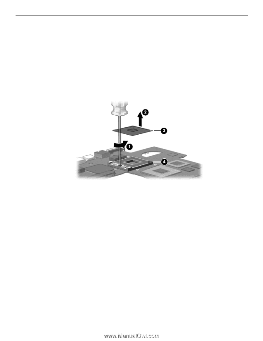
Removal and replacement procedures i. Display assembly (see "Display assembly" on page 29). j. Top cover (see "Top cover" on page 23). k. System board (see "System board" on page 41). l. Fan/heat sink assembly (see "Fan/heat sink assembly" on page 44). Remove the processor: 1. Use a flat-bladed screwdriver to turn the processor locking screw 1 one-half turn counterclockwise until you hear a click. 2. Lift the processor 2 straight up and remove it. ✎ When you install the processor, the gold triangle 3 on the processor must be aligned with the triangle 4 embossed on the processor socket. Reverse this procedure to install the processor. 4-50 Maintenance and Service Guide
-
 1
1 -
2
-
3
-
4
-
5
-
6
-
7
-
8
-
9
-
10
-
11
-
12
-
13
-
14
-
15
-
16
-
17
-
18
-
19
-
20
-
21
-
22
-
23
-
24
-
25
-
26
-
27
-
28
-
29
-
30
-
31
-
32
-
33
-
34
-
35
-
36
-
37
-
38
-
39
-
40
-
41
-
42
-
43
-
44
-
45
-
46
-
47
-
48
-
49
-
50
-
51
-
52
-
53
-
54
-
55
-
56
-
57
-
58
-
59
-
60
-
61
-
62
-
63
-
64
-
65
-
66
-
67
-
68
-
69
-
70
-
71
-
72
-
73
-
74
-
75
-
76
-
77
-
78
-
79
-
80
-
 81
81 -
 82
82 -
 83
83 -
 84
84 -
 85
85 -
 86
86 -
 87
87 -
 88
88 -
 89
89 -
 90
90 -
 91
91 -
92
-
93
-
94
-
95
-
96
-
97
-
98
-
99
-
100
-
101
-
102
-
103
-
104
-
105
-
106
-
107
-
108
-
109
-
110
-
111
-
112
-
113
-
114
-
115
-
116
-
117
-
118
-
119
-
120
-
121
-
122
-
123
-
124
-
125
-
126
-
127
-
128
-
129
-
130
-
131
-
132
-
133
-
134
-
135
 |
 |
4–50
Maintenance and Service Guide
Removal and replacement procedures
i.
Display assembly (see
“Display assembly” on page 29
).
j.
Top cover (see
“Top cover” on page 23
).
k.
System board (see
“System board” on page 41
).
l.
Fan/heat sink assembly (see
“Fan/heat sink assembly” on page 44
).
Remove the processor:
1. Use a flat-bladed screwdriver to turn the processor locking screw
1
one-half turn counterclockwise until you
hear a click.
2. Lift the processor
2
straight up and remove it.
✎
When you install the processor, the gold triangle
3
on the processor must be aligned with the triangle
4
embossed
on the processor socket.
Reverse this procedure to install the processor.