HP Presario CQ61-200 Compaq Presario CQ71 Notebook PC and HP G71 Notebook PC - - Page 92
Processor
 |
View all HP Presario CQ61-200 manuals
Add to My Manuals
Save this manual to your list of manuals |
Page 92 highlights
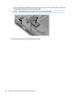
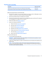
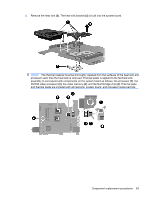
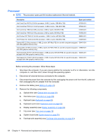
Processor NOTE: The processor spare part kit includes replacement thermal material. Description Spare part number Intel Core2 Duo P8700 (2.53-GHz processor, 3-MB L2 cache, 1066-MHz FSB) Intel Core2 Duo P7450 (2.13-GHz processor, 3-MB L2 cache, 1066-MHz FSB) Intel Core2 Duo T6600 (2.2-GHz processor, 2-MB L2 cache, 800-MHz FSB) 507960-001 507965-001 513593-001 Intel Core2 Duo T6400 (2.0-GHz processor, 2-MB L2 cache, 800-MHz FSB) 513592-001 Intel Pentium DC T3400 (2.16-GHz processor, 1-MB L2 cache, 667-MHz FSB) 509549-001 Intel Pentium DC T4200 (2.00-GHz processor, 1-MB L2 cache, 800-MHz FSB) 513599-001 Celeron 900 2.2-GHz processor, (1-MB L2 cache, 667-Mhz FSB, for use with computers equipped 534419-001 with UMA graphics memory only) Celeron 585 2.16-GHz processor, (1-MB L2 cache, 667-MHz FSB, for use with computers equipped 519898-001 with UMA graphics memory only) Intel Celeron DC T1700 1.83-GHz processor, (1-MB L2 cache, 667-MHz FSB, for use with computers 534084-001 equipped with UMA graphics memory only) Intel Celeron DC T1600 1.66-GHz processor, (1-MB L2 cache, 667-MHz FSB, for use with computers 532324-001 equipped with UMA graphics memory only) Before removing the processor, follow these steps: 1. Shut down the computer. If you are unsure whether the computer is off or in Hibernation, turn the computer on, and then shut it down through the operating system. 2. Disconnect all external devices connected to the computer. 3. Disconnect the power from the computer by first unplugging the power cord from the AC outlet and then unplugging the AC adapter from the computer. 4. Remove the battery (see Battery on page 47). 5. Remove the following components: a. Optical drive (see Optical drive on page 53) b. Hard drive (see Hard drive on page 56) c. Keyboard (see Keyboard on page 60) d. Keyboard cover (see Keyboard cover on page 63) e. Display assembly (see Display assembly on page 66) f. Top cover (see Top cover on page 72) g. System board (see System board on page 76) h. Fan/heat sink assembly (see Fan/heat sink assembly on page 81) 84 Chapter 4 Removal and replacement procedures
-
 1
1 -
2
-
3
-
4
-
5
-
6
-
7
-
8
-
9
-
10
-
11
-
12
-
13
-
14
-
15
-
16
-
17
-
18
-
19
-
20
-
21
-
22
-
23
-
24
-
25
-
26
-
27
-
28
-
29
-
30
-
31
-
32
-
33
-
34
-
35
-
36
-
37
-
38
-
39
-
40
-
41
-
42
-
43
-
44
-
45
-
46
-
47
-
48
-
49
-
50
-
51
-
52
-
53
-
54
-
55
-
56
-
57
-
58
-
59
-
60
-
61
-
62
-
63
-
64
-
65
-
66
-
67
-
68
-
69
-
70
-
71
-
72
-
73
-
74
-
75
-
76
-
77
-
78
-
79
-
80
-
81
-
82
-
83
-
84
-
85
-
86
-
 87
87 -
 88
88 -
 89
89 -
 90
90 -
 91
91 -
 92
92 -
 93
93 -
 94
94 -
 95
95 -
 96
96 -
 97
97 -
98
-
99
-
100
-
101
-
102
-
103
-
104
-
105
-
106
-
107
-
108
-
109
-
110
-
111
-
112
-
113
-
114
-
115
-
116
-
117
-
118
-
119
-
120
-
121
-
122
-
123
-
124
-
125
-
126
-
127
-
128
-
129
-
130
-
131
-
132
-
133
-
134
-
135
-
136
-
137
-
138
-
139
-
140
-
141
-
142
-
143
-
144
 |
 |
