HP Presario V4100 HP Pavilion dv4000 Notebook PC and Compaq Presario V4000 Not - Page 177
Fan Assembly, Heat Sink
 |
View all HP Presario V4100 manuals
Add to My Manuals
Save this manual to your list of manuals |
Page 177 highlights
Removal and Replacement Procedures 5.19 Fan Assembly ✎ The fan assembly is included in the heat sink assembly spare part kit, spare part number 384622-001. Refer to Section 5.10, "Heat Sink," for information on removing the heat sink.) 1. Prepare the computer for disassembly (Section 5.3) and remove the following components: a. Hard drive (Section 5.4) b. Switch cover (Section 5.12) c. Keyboard (Section 5.13) d. Display assembly (Section 5.14) e. Top cover (Section 5.15) f. System board (Section 5.18) 2. Turn the system board upside down with the right side toward you. Maintenance and Service Guide 5-73
-
 1
1 -
2
-
3
-
4
-
5
-
6
-
7
-
8
-
9
-
10
-
11
-
12
-
13
-
14
-
15
-
16
-
17
-
18
-
19
-
20
-
21
-
22
-
23
-
24
-
25
-
26
-
27
-
28
-
29
-
30
-
31
-
32
-
33
-
34
-
35
-
36
-
37
-
38
-
39
-
40
-
41
-
42
-
43
-
44
-
45
-
46
-
47
-
48
-
49
-
50
-
51
-
52
-
53
-
54
-
55
-
56
-
57
-
58
-
59
-
60
-
61
-
62
-
63
-
64
-
65
-
66
-
67
-
68
-
69
-
70
-
71
-
72
-
73
-
74
-
75
-
76
-
77
-
78
-
79
-
80
-
81
-
82
-
83
-
84
-
85
-
86
-
87
-
88
-
89
-
90
-
91
-
92
-
93
-
94
-
95
-
96
-
97
-
98
-
99
-
100
-
101
-
102
-
103
-
104
-
105
-
106
-
107
-
108
-
109
-
110
-
111
-
112
-
113
-
114
-
115
-
116
-
117
-
118
-
119
-
120
-
121
-
122
-
123
-
124
-
125
-
126
-
127
-
128
-
129
-
130
-
131
-
132
-
133
-
134
-
135
-
136
-
137
-
138
-
139
-
140
-
141
-
142
-
143
-
144
-
145
-
146
-
147
-
148
-
149
-
150
-
151
-
152
-
153
-
154
-
155
-
156
-
157
-
158
-
159
-
160
-
161
-
162
-
163
-
164
-
165
-
166
-
167
-
168
-
169
-
170
-
171
-
 172
172 -
 173
173 -
 174
174 -
 175
175 -
 176
176 -
 177
177 -
 178
178 -
 179
179 -
 180
180 -
 181
181 -
 182
182 -
183
-
184
-
185
-
186
-
187
-
188
-
189
-
190
-
191
-
192
-
193
-
194
-
195
-
196
-
197
-
198
-
199
-
200
-
201
-
202
-
203
-
204
-
205
-
206
-
207
-
208
-
209
-
210
-
211
-
212
-
213
-
214
-
215
-
216
-
217
-
218
-
219
-
220
-
221
-
222
-
223
-
224
-
225
-
226
-
227
-
228
-
229
-
230
-
231
-
232
-
233
-
234
-
235
-
236
-
237
-
238
-
239
-
240
-
241
-
242
-
243
-
244
-
245
-
246
-
247
-
248
-
249
-
250
-
251
-
252
-
253
-
254
-
255
-
256
-
257
-
258
-
259
-
260
-
261
-
262
-
263
-
264
-
265
-
266
 |
 |
Removal and Replacement Procedures
Maintenance and Service Guide
5–73
5.19
Fan Assembly
✎
The fan assembly is included in the heat sink assembly spare
part kit, spare part number 384622-001. Refer to
Section 5.10,
“Heat Sink,”
for information on removing the heat sink.)
1. Prepare the computer for disassembly (
Section 5.3
)
and remove the following components:
a.
Hard drive (
Section 5.4
)
b.
Switch cover (
Section 5.12
)
c.
Keyboard (
Section 5.13
)
d.
Display assembly (
Section 5.14
)
e.
Top cover (
Section 5.15
)
f.
System board (
Section 5.18
)
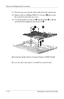
2. Turn the system board upside down with the right side
toward you.