HP Presario V6700 Compaq Presario V6500, V6600, and V6700 Notebook PCs - Maint - Page 67
Two covers on the lower-inside edge of the bezel
 |
View all HP Presario V6700 manuals
Add to My Manuals
Save this manual to your list of manuals |
Page 67 highlights
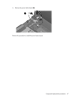
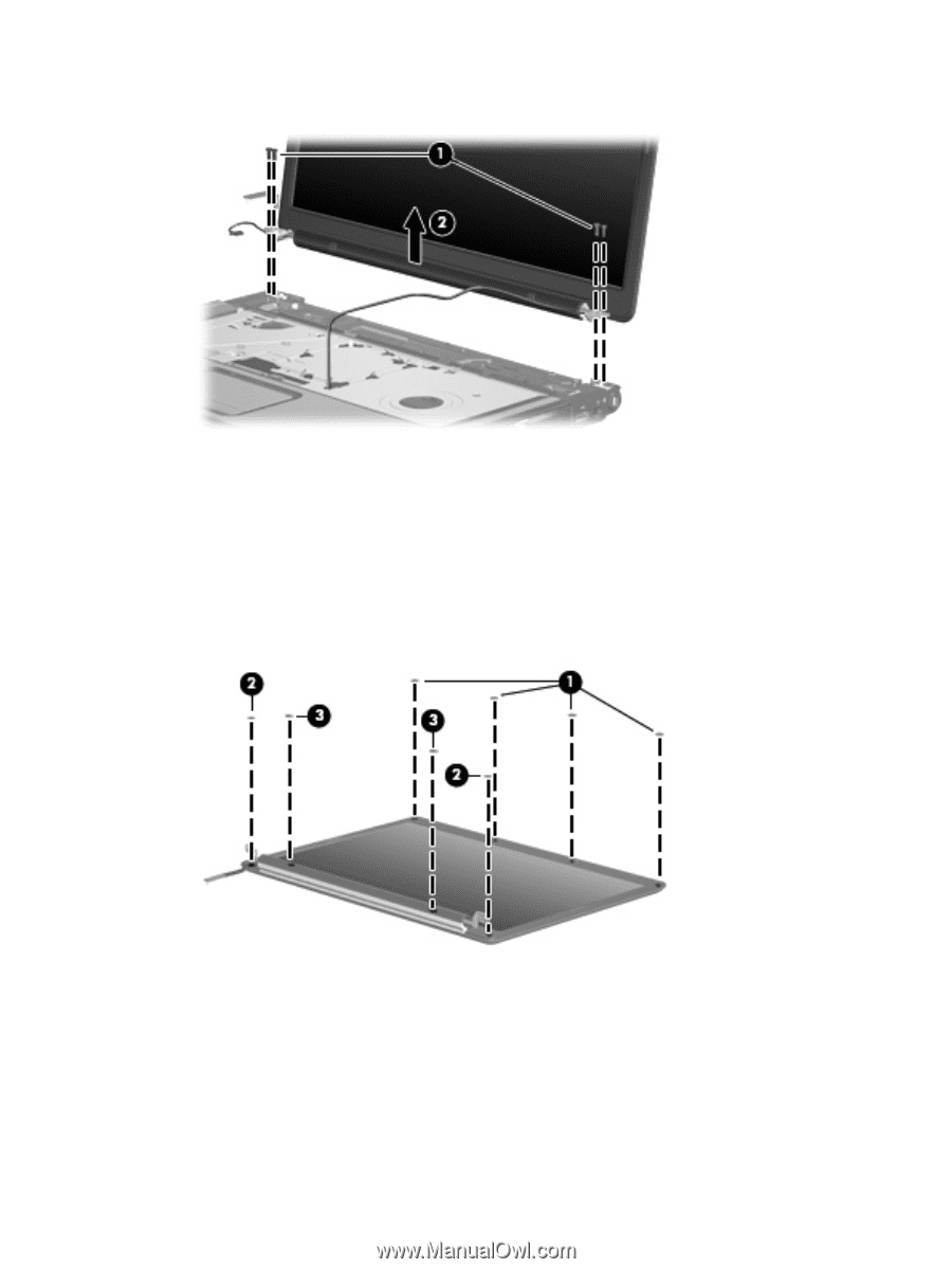
5. Remove the display assembly (2). 6. If it is necessary to replace the display bezel or any of the display assembly internal components, remove the following screw covers: (1) Four covers on the top edge of the bezel (2) Two covers on the lower bezel edges (3) Two covers on the lower-inside edge of the bezel The display rubber screw covers are included in the Display Screw Kit, spare part number 431400-001. Component replacement procedures 59
-
 1
1 -
2
-
3
-
4
-
5
-
6
-
7
-
8
-
9
-
10
-
11
-
12
-
13
-
14
-
15
-
16
-
17
-
18
-
19
-
20
-
21
-
22
-
23
-
24
-
25
-
26
-
27
-
28
-
29
-
30
-
31
-
32
-
33
-
34
-
35
-
36
-
37
-
38
-
39
-
40
-
41
-
42
-
43
-
44
-
45
-
46
-
47
-
48
-
49
-
50
-
51
-
52
-
53
-
54
-
55
-
56
-
57
-
58
-
59
-
60
-
61
-
 62
62 -
 63
63 -
 64
64 -
 65
65 -
 66
66 -
 67
67 -
 68
68 -
 69
69 -
 70
70 -
 71
71 -
 72
72 -
73
-
74
-
75
-
76
-
77
-
78
-
79
-
80
-
81
-
82
-
83
-
84
-
85
-
86
-
87
-
88
-
89
-
90
-
91
-
92
-
93
-
94
-
95
-
96
-
97
-
98
-
99
-
100
-
101
-
102
-
103
-
104
-
105
-
106
-
107
-
108
-
109
-
110
-
111
-
112
-
113
-
114
-
115
-
116
-
117
-
118
-
119
-
120
-
121
-
122
-
123
-
124
-
125
-
126
-
127
-
128
-
129
-
130
-
131
-
132
-
133
-
134
-
135
-
136
-
137
-
138
-
139
-
140
-
141
-
142
-
143
-
144
-
145
-
146
-
147
-
148
 |
 |
5
.
Remove the display assembly
(2)
.
6
.
If it is necessary to replace the display bezel or any of the display assembly internal components,
remove the following screw covers:
(1)
Four covers on the top edge of the bezel
(2)
Two covers on the lower bezel edges
(3)
Two covers on the lower-inside edge of the bezel
The display rubber screw covers are included in the Display Screw Kit, spare part number
431400-001.
Component replacement procedures
59