HP ProBook 4425s HP ProBook 4325s, 4326s and 4425s Notebook PCs - Maintenance - Page 102
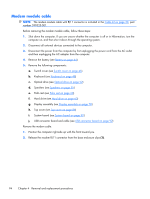
Modem module cable
 |
View all HP ProBook 4425s manuals
Add to My Manuals
Save this manual to your list of manuals |
Page 102 highlights
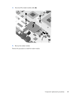
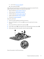
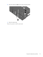
Modem module cable NOTE: The modem module cable with RJ11 connector is included in the Cable kit on page 30, part number 599525-001. Before removing the modem module cable, follow these steps: 1. Shut down the computer. If you are unsure whether the computer is off or in Hibernation, turn the computer on, and then shut it down through the operating system. 2. Disconnect all external devices connected to the computer. 3. Disconnect the power from the computer by first unplugging the power cord from the AC outlet and then unplugging the AC adapter from the computer. 4. Remove the battery (see Battery on page 44). 5. Remove the following components: a. Switch cover (see Switch cover on page 46) b. Keyboard (see Keyboard on page 48) c. Optical drive (see Optical drive on page 52) d. Speakers (see Speakers on page 55) e. Palm rest (see Palm rest on page 60) f. Hard drive (see Hard drive on page 63) g. Display assembly (see Display assembly on page 78) h. Top cover (see Top cover on page 86) i. System board (see System board on page 90) j. USB connector board and cable (see USB connector board on page 92) Remove the modem cable. 1. Position the computer right-side up with the front toward you. 2. Release the modem RJ11 connector from the base enclosure clips (1). 94 Chapter 4 Removal and replacement procedures
-
 1
1 -
2
-
3
-
4
-
5
-
6
-
7
-
8
-
9
-
10
-
11
-
12
-
13
-
14
-
15
-
16
-
17
-
18
-
19
-
20
-
21
-
22
-
23
-
24
-
25
-
26
-
27
-
28
-
29
-
30
-
31
-
32
-
33
-
34
-
35
-
36
-
37
-
38
-
39
-
40
-
41
-
42
-
43
-
44
-
45
-
46
-
47
-
48
-
49
-
50
-
51
-
52
-
53
-
54
-
55
-
56
-
57
-
58
-
59
-
60
-
61
-
62
-
63
-
64
-
65
-
66
-
67
-
68
-
69
-
70
-
71
-
72
-
73
-
74
-
75
-
76
-
77
-
78
-
79
-
80
-
81
-
82
-
83
-
84
-
85
-
86
-
87
-
88
-
89
-
90
-
91
-
92
-
93
-
94
-
95
-
96
-
 97
97 -
 98
98 -
 99
99 -
 100
100 -
 101
101 -
 102
102 -
 103
103 -
 104
104 -
 105
105 -
 106
106 -
 107
107 -
108
-
109
-
110
-
111
-
112
-
113
-
114
-
115
-
116
-
117
-
118
-
119
-
120
-
121
-
122
-
123
-
124
-
125
-
126
-
127
-
128
-
129
-
130
-
131
-
132
-
133
-
134
-
135
-
136
-
137
-
138
-
139
-
140
-
141
-
142
-
143
-
144
-
145
-
146
-
147
-
148
-
149
-
150
-
151
-
152
-
153
-
154
-
155
-
156
-
157
-
158
-
159
-
160
-
161
-
162
 |
 |