HP ProLiant BL495c Dynamic Power Capping TCO and Best Practices White Paper (E - Page 10
Setting Dynamic Power Cap with HP BladeSystem infrastructure, TCO benchmarking see Appendix
 |
View all HP ProLiant BL495c manuals
Add to My Manuals
Save this manual to your list of manuals |
Page 10 highlights
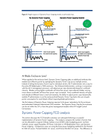
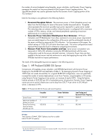
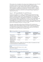
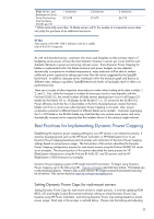
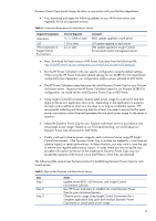
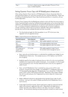
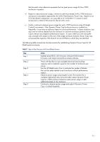
Step 4 Continue to observe power usage and adjust if Dynamic Power Cap is invoked frequently. Setting Dynamic Power Cap with HP BladeSystem infrastructure When setting a Dynamic Power Cap for an HP BladeSystem enclosure, the process follow the same general principles as our rack-mount example with a few important differences. Please note that setting and adjusting Dynamic Power Caps should always be done in conjunction with your facilities department. Dynamic Power Capping within the BladeSystem enclosure works well when the servers support a variety of general purpose computing workloads because applications such as accounting, email, webservers, and database servers typically do not experience peak demands at exactly the same time. An enclosure devoted to high-performance computing such as financial modeling or scientific computing would not see as much power reclaimed. These scale-out applications typically have synchronized workloads that peak and idle concurrently. • First, download and apply the following updates to your HP ProLiant server (see Appendix for list of supported servers): Table 6. Component Requirement for BladeSytem Servers Required Component ROM BIOS iLO Onboard Administrator IPM component of Insight Control Environment Version Required 11/1/2008 or later 1.70 or later 2.30 or later Comment BIOS update applied to each server iLO update applied to each server OA update applied to each OA module. 2.0 or later IPM update applied to Insight Control Environment central management server. • Next, meet with your facilities person, to understand the available power budget for your HP BladeSystem infrastructure. This example assumes a 30 A 3-phase circuit with 8.6 kW of capacity. • Establish a goal for the number of enclosures that you wish to fit on the circuit and divide available circuit capacity by the number of enclosures. In our example, we will set a goal of two enclosures per circuit. We then divide the 8.6 KW circuits into two segments of 4300 W each. • Next, use the HP BladeSystem Sizer to calculate how many servers will fit in each enclosure, using the given power budget. For the BL460c G1 configuration used in our TCO benchmarking (see Appendix), the BladeSystem Sizer indicates that 10 BL460 G1 servers will fit in each c7000 enclosure (20 total). Depending on the number of blades that will fit into the enclosure, the IT department may want to adjust the "enclosure per circuit" goal. • Deploy additional enclosures as appropriate and set Dynamic Power Caps for each enclosure. Insert up to the number of blades specified by the HP BladeSystem Sizer in each enclosure. • Using Insight Control Environment, observe peak power usage for a period of time that aligns to the enclosure's application duty cycle. Depending on the applications in question, this duty cycle could be as short as a few days or as long as a calendar quarter. HP recommends collecting and observing data for at least one week to ensure 10
-
 1
1 -
2
-
3
-
4
-
 5
5 -
 6
6 -
 7
7 -
 8
8 -
 9
9 -
 10
10 -
 11
11 -
 12
12 -
 13
13 -
 14
14 -
 15
15
 |
 |