HP ProLiant DL160 HP ProLiant DL160 Generation 5 Server Maintenance and Servic - Page 27
Connectors, Switches, and LEDs, Connectors and components, Front panel components
 |
View all HP ProLiant DL160 manuals
Add to My Manuals
Save this manual to your list of manuals |
Page 27 highlights
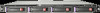
Connectors, Switches, and LEDs This chapter contains illustrations and tables identifying and describing the connectors, switches, buttons, and LED indicators located on the front panel, rear panel, system board and hard drives of the HP ProLiant DL160 G5 server. Connectors and components Front panel components Figure 1 Front panel components Item 1 2 3 4 5 6 7 8 9 10 11 Description Thumbscrews for rack mounting Optical disk drive bay Serial number pull tab Two front USB 2.0 ports Unit identification (UID) LED button System health LED NIC1 LED NIC2 LED Power button with LED indicator (bicolor: green and amber) HDD LED Hard disk drive (HDD) bays 1, 2, 3, and 4 Connectors, Switches, and LEDs 27
-
 1
1 -
2
-
3
-
4
-
5
-
6
-
7
-
8
-
9
-
10
-
11
-
12
-
13
-
14
-
15
-
16
-
17
-
18
-
19
-
20
-
21
-
 22
22 -
 23
23 -
 24
24 -
 25
25 -
 26
26 -
 27
27 -
 28
28 -
 29
29 -
 30
30 -
 31
31 -
 32
32 -
33
-
34
-
35
-
36
-
37
-
38
-
39
-
40
-
41
-
42
-
43
-
44
-
45
-
46
-
47
-
48
-
49
-
50
-
51
-
52
-
53
-
54
-
55
-
56
-
57
-
58
-
59
-
60
-
61
-
62
-
63
-
64
-
65
-
66
-
67
-
68
-
69
-
70
-
71
-
72
-
73
-
74
-
75
-
76
-
77
-
78
-
79
-
80
-
81
-
82
-
83
-
84
-
85
-
86
-
87
-
88
-
89
-
90
-
91
-
92
-
93
-
94
-
95
-
96
-
97
-
98
-
99
 |
 |

Connectors, Switches, and LEDs
27
Connectors, Switches, and LEDs
This chapter contains illustrations and tables identifying and describing the connectors, switches,
buttons, and LED indicators located on the front panel, rear panel, system board and hard drives of
the HP ProLiant DL160 G5 server.
Connectors and components
Front panel components
Figure 1
Front panel components
Item
Description
1
Thumbscrews for rack mounting
2
Optical disk drive bay
3
Serial number pull tab
4
Two front USB 2.0 ports
5
Unit identification (UID) LED button
6
System health LED
7
NIC1 LED
8
NIC2 LED
9
Power button with LED indicator (bicolor: green and amber)
10
HDD LED
11
Hard disk drive (HDD) bays 1, 2, 3, and 4