HP ProLiant DL185 HP ProLiant DL185 Generation 5 Server Installation Sheet - Page 2
Opening the Server, Installing a Hard Drive, Installing Front Optical Disk Drive, Installing
 |
View all HP ProLiant DL185 manuals
Add to My Manuals
Save this manual to your list of manuals |
Page 2 highlights
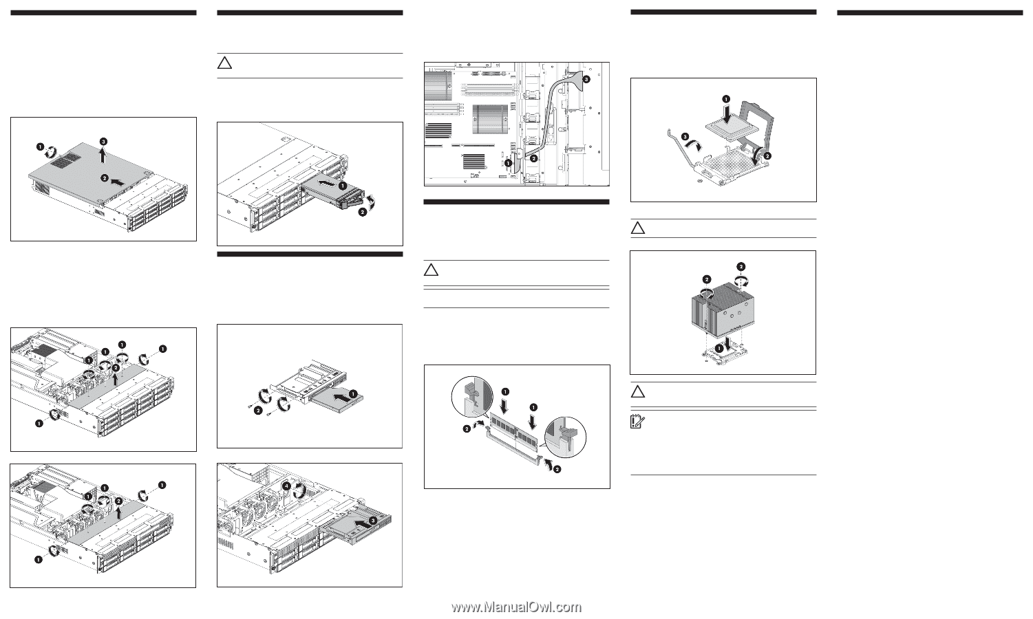
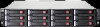
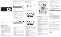
Opening the Server The top cover and the top middle cover are detachable. You need to remove the top cover before you can remove or replace a server component. The top middle cover is removed to service the HDD PCA. To remove the top cover: 1. Loosen the captive screw on the rear panel with a T-10 screwdriver. 2. Slide the cover approximately 1.25 cm (0.5 in) toward the rear of the unit and then lift the cover to detach it from the chassis. 3. Lift the top cover away from the chassis. Figure 7 Removing the top cover Installing a Hard Drive The drive bays on the front panel can accommodate up to twelve hard drives (12-drive models). CAUTION: Drives can be damaged by static electricity. Before handling drives, touch an unpainted metal surface to discharge static electricity. To install a hard drive in the server: 1. Push the hard drive assembly into the drive bay until it stops. 2. Press the HDD carrier latch inward until it clicks. Figure 10 Installing the hard drive assembly (12-drive model shown) To route the ODD cable: 1. Connect the cable connector of the black part to the MB. 2. Put the other part of cable through the cable hole. 3. Connect the blue connector of the cable to the optical drive. Figure 13 ODD cable routing Installing a Processor To install the processor: 1. Insert the processor into the socket, using the key on the processor. 2. Engage the retention plate and the load lever. Figure 15 Installing a processor Additional Documentation For additional documentation, refer to the HP ProLiant DL185 Generation 5 Server Support CD. You can also access additional information and documentation from the HP external website, either by connecting directly or through the Support CD. Legal notices © Copyright 2007 Hewlett-Packard Development Company, L.P. The information contained herein is subject to change without notice. The only warranties for HP products and services are set forth in the express warranty statements accompanying such products and services. Nothing herein should be construed as constituting an additional warranty. HP shall not be liable for technical or editorial errors or omissions contained herein. To remove the top middle cover: 1. For the 12 HDD version, remove the five screws (one on each side of the chassis and three on the top middle cover) that secure the top middle cover to the chassis with a T-15 screwdriver. (figure 8) For the 8 HDD version, remove the four screws (one on each side of the chassis and two on the top middle cover) that secure the top middle cover to the chassis with a T-15 screwdriver. (figure 9) 2. Lift the top middle cover away from the chassis. Figure 8 Removing the top middle cover (for 12 HDD version) Installing Front Optical Disk Drive 1. Align the optical drive in the carrier and install drive. 2. Secure the optical drive to the carrier with the two mounting screws. 3. Slide the optical drive assembly into the chassis. 4. Secure the optical drive to the chassis with the screw. Figure 11 Assembling the optical drive and carrier Figure 9 Removing the top middle cover (for 8 HDD version) Figure 12 Installing the optical drive assembly Installing a Memory Module • Supported configuration: o Two DIMMs per processor : 1A, 2A for CPU1 ; 5C, 6C for CPU2. o Four DIMMs per processor : 1A, 2A, 3B, 4B for CPU1 ; 5C, 6C, 7D, 8D for CPU2. CAUTION: DIMMs can be damaged by improper handling. Always use an anti-static wrist strap and grounding mat, and discharge static electricity before touching DIMMs. NOTE: Refer to "System Board Components" in this document for the DIMM locations. To install a memory module: 1. Align the notch on the bottom edge of the module with the keyed surface of the DIMM slot and then press the module fully into the slot. 2. Firmly press the holding clips inward to secure the memory module in place. Figure 14 Installing a memory module For processor removal, reverse the above installation procedures. CAUTION: Align pin 1 on the processor with pin 1 on the processor socket, or pin damage will occur. Figure 16 Installing the heat sink assembly CAUTION: Be sure that the heat sink sits squarely on the processor, or overheating and damage to the processor may occur. IMPORTANT: If the heat sink has been removed for any reason, it is critical that you apply more thermal interface material to the integrated heat spreader on the processor to ensure proper thermal bonding between the processor and the heat sink. Clean the contact surface of both the processor and heat sink with an alcohol pad, then re-apply an HP-approved thermal interface material before reinstalling the processor. Use a pattern of five dots when applying the thermal interface material-one dot in the center, and one dot at each corner. DIMM slots are structured to ensure proper installation. If you insert a DIMM but it does not fit easily into the slot, you may have inserted it incorrectly. Reverse the orientation of the DIMM and insert it again.
-
 1
1 -
 2
2
 |
 |