HP ProLiant DL280 HP ProLiant DL288 G6 Server Maintenance and Service Guide
HP ProLiant DL280 Manual
 |
View all HP ProLiant DL280 manuals
Add to My Manuals
Save this manual to your list of manuals |
HP ProLiant DL280 manual content summary:
- HP ProLiant DL280 | HP ProLiant DL288 G6 Server Maintenance and Service Guide - Page 1
HP ProLiant DL288 G6 Server Maintenance and Service Guide Part number 663204-001 First edition July 2011 - HP ProLiant DL280 | HP ProLiant DL288 G6 Server Maintenance and Service Guide - Page 2
to change without notice. The only warranties for HP products and services are set forth in the express warranty statements accompanying such products and services. Nothing herein should be construed as constituting an additional warranty. HP shall not be liable for technical or editorial errors - HP ProLiant DL280 | HP ProLiant DL288 G6 Server Maintenance and Service Guide - Page 3
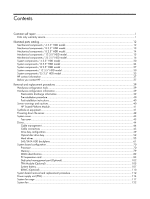
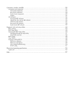
self repair ...1 Parts only warranty service...1 Illustrated parts catalog ...12 configuration tools ...39 Hardware configuration information...39 Electrostatic discharge information ...39 Pre-installation procedure ...40 Post-installation instructions ...40 Server warnings and cautions...40 HP - HP ProLiant DL280 | HP ProLiant DL288 G6 Server Maintenance and Service Guide - Page 4
menu bar ...142 BIOS update ...148 Clear CMOS...148 Power-On Self-Test (POST)...148 POST error indicators ...149 POST error descriptions ...149 POST related troubleshooting...150 SETSYS utility...151 Physical and operating specifications 152 System unit...152 Index ...157 - HP ProLiant DL280 | HP ProLiant DL288 G6 Server Maintenance and Service Guide - Page 5
period HP (or HP service providers or service partners) identifies that the repair can be accomplished by the use of a CSR part, HP will ship is required, you can call the HP Technical Support Center and a technician will help you over the telephone. HP specifies in the materials shipped with a - HP ProLiant DL280 | HP ProLiant DL288 G6 Server Maintenance and Service Guide - Page 6
pièce défectueuse, HP se réserve le droit de vous facturer les coûts de remplacement. Dans le cas d'une pièce CSR, HP supporte l'ensemble des frais le site Web HP (http://www.hp.com/go/selfrepair). Service de garantie "pièces seules" Votre garantie limitée HP peut inclure un service de garantie "pi - HP ProLiant DL280 | HP ProLiant DL288 G6 Server Maintenance and Service Guide - Page 7
due categorie di parti CSR: • Obbligatorie-Parti che devono essere necessariamente riparate dal cliente. Se il cliente ne affida la riparazione ad HP, deve sostenere le spese di spedizione e di manodopera per il servizio. • Opzionali-Parti la cui riparazione da parte del cliente è facoltativa. Si - HP ProLiant DL280 | HP ProLiant DL288 G6 Server Maintenance and Service Guide - Page 8
Sie jedoch den Austausch dieser Teile von HP vornehmen lassen möchten, können bei diesem Service je nach den für Ihr Produkt vorgesehenen verfügbar. Wenn Sie Hilfe benötigen, können Sie das HP technische Support Center anrufen und sich von einem Mitarbeiter per Telefon helfen lassen. Den - HP ProLiant DL280 | HP ProLiant DL288 G6 Server Maintenance and Service Guide - Page 9
componentes CSR se clasifican en dos categorías: • Obligatorio-componentes para los que la reparación por parte del usuario es obligatoria. Si solicita a HP que realice la sustitución de estos componentes, tendrá que hacerse cargo de los gastos de desplazamiento y de mano de obra de dicho servicio - HP ProLiant DL280 | HP ProLiant DL288 G6 Server Maintenance and Service Guide - Page 10
onderdelen worden CSR-onderdelen (Customer Self Repair) genoemd. Als HP (of een HP Service Partner) bij de diagnose vaststelt dat de reparatie kan gebracht, afhankelijk van het type garantieservice voor het product. OPMERKING: Sommige HP onderdelen zijn niet ontwikkeld voor reparatie door de klant - HP ProLiant DL280 | HP ProLiant DL288 G6 Server Maintenance and Service Guide - Page 11
Peças cujo reparo feito pelo cliente é opcional. Essas peças também são projetadas para o reparo feito pelo cliente. No entanto, se desejar que a HP as substitua, pode haver ou não a cobrança de taxa adicional, dependendo do tipo de serviço de garantia destinado ao produto. OBSERVAÇÃO: Algumas peças - HP ProLiant DL280 | HP ProLiant DL288 G6 Server Maintenance and Service Guide - Page 12
Customer self repair 8 - HP ProLiant DL280 | HP ProLiant DL288 G6 Server Maintenance and Service Guide - Page 13
Customer self repair 9 - HP ProLiant DL280 | HP ProLiant DL288 G6 Server Maintenance and Service Guide - Page 14
Customer self repair 10 - HP ProLiant DL280 | HP ProLiant DL288 G6 Server Maintenance and Service Guide - Page 15
Customer self repair 11 - HP ProLiant DL280 | HP ProLiant DL288 G6 Server Maintenance and Service Guide - Page 16
SCR, M2-0.4x.2.1mm, 6G, PH SCR TT, 6-32x.160,SLT-T15 BLANK, PS, NONPERF, IDOF REAR I/O PANEL, LC2UG6 5 Top cover Spare Part Number 507256-001 573091-001 507305-001 507260-001 507262-001 Customer self repair Mandatory1 Mandatory1 Mandatory1 Mandatory1 Mandatory1 Illustrated parts catalog 12 - HP ProLiant DL280 | HP ProLiant DL288 G6 Server Maintenance and Service Guide - Page 17
SCR, M2-0.4x.2.1mm, 6G, PH SCR TT, 6-32x.160,SLT-T15 BLANK, PS, NONPERF, IDOF REAR I/O PANEL, LC2UG6 5 Top cover Spare Part Number 507256-001 573091-001 507305-001 507260-001 507262-001 Customer self repair Mandatory1 Mandatory1 Mandatory1 Mandatory1 Mandatory1 Illustrated parts catalog 13 - HP ProLiant DL280 | HP ProLiant DL288 G6 Server Maintenance and Service Guide - Page 18
SCR, M2-0.4x.2.1mm, 6G, PH SCR TT, 6-32x.160,SLT-T15 BLANK, PS, NONPERF, IDOF REAR I/O PANEL, LC2UG6 5 Top cover Spare Part Number 507256-001 573091-001 507253-001 507260-001 507262-001 Customer self repair Mandatory1 Mandatory1 Mandatory1 Mandatory1 Mandatory1 Illustrated parts catalog 14 - HP ProLiant DL280 | HP ProLiant DL288 G6 Server Maintenance and Service Guide - Page 19
SCR, M2-0.4x.2.1mm, 6G, PH SCR TT, 6-32x.160,SLT-T15 BLANK, PS, NONPERF, IDOF REAR I/O PANEL, LC2UG6 5 Top cover Spare Part Number 507256-001 573091-001 587326-001 536390-001 507262-001 Customer self repair Mandatory1 Mandatory1 Mandatory1 Mandatory1 Mandatory1 Illustrated parts catalog 15 - HP ProLiant DL280 | HP ProLiant DL288 G6 Server Maintenance and Service Guide - Page 20
NONPERF, IDOF REAR I/O PANEL, LC2UG6 5 Top cover Spare Part Number 507256-001 573091-001 530946-001 507260-001 Customer self repair Mandatory1 HP replace them for you, there may or may not be additional charges, depending on the type of warranty service designated for your product. 3No-Some HP - HP ProLiant DL280 | HP ProLiant DL288 G6 Server Maintenance and Service Guide - Page 21
optional ist. Diese Teile sind auch für Customer Self Repair ausgelegt. Wenn Sie jedoch den Austausch dieser Teile von HP vornehmen lassen möchten, können bei diesem Service je nach den für Ihr Produkt vorgesehenen Garantiebedingungen zusätzliche Kosten anfallen. 3No: Kein-Einige Teile sind nicht - HP ProLiant DL280 | HP ProLiant DL288 G6 Server Maintenance and Service Guide - Page 22
garantieservice voor het product. 3No: Nee-Sommige HP onderdelen zijn niet Service Partner worden vervangen. Deze onderdelen worden in de geïllustreerde onderdelencatalogus aangemerkt met "Nee". 1Mandatory: Obrigatória-Peças cujo reparo feito pelo cliente é obrigatório. Se desejar que a HP - HP ProLiant DL280 | HP ProLiant DL288 G6 Server Maintenance and Service Guide - Page 23
Illustrated parts catalog 19 - HP ProLiant DL280 | HP ProLiant DL288 G6 Server Maintenance and Service Guide - Page 24
The system supports five kinds of HDD configurations, three types of PCI cage and three types of power supply unit. The following table lists the detailed system configurations. Table 6 System Configurations System model PCI cage Power supply unit 4 3.5" HDD model 8 3.5" HDD model 8 2.5" HDD - HP ProLiant DL280 | HP ProLiant DL288 G6 Server Maintenance and Service Guide - Page 25
5600 series processors 2 Power supplies (all support hot-plug) Power supply 460 W Power DC Converter Power Backplane Assy. 4 System fans 5 Memory modules Registered DIMMs (RDIMMs) DIMM, 2GB 2Rx8 PC3- 80W 7 Processor heat sinks Spare Part Number 507255-001 608865-001 Customer self repair - HP ProLiant DL280 | HP ProLiant DL288 G6 Server Maintenance and Service Guide - Page 26
hot-plug SATA hard drives with carriers 160 GB 7,200 rpm 250 GB 7,200 rpm 500 GB 7,200 rpm 750 GB 7,200 rpm Spare Part Number Customer self repair 481428-001 481429-001 Mandatory1 Mandatory1 376594-001 376595-001 432146-001 456896-001 454274-001 461288-001 461289-001 Mandatory1 Mandatory1 - HP ProLiant DL280 | HP ProLiant DL288 G6 Server Maintenance and Service Guide - Page 27
riser card PCI-E x16 13 TPM Module (Must be replaced with system board if present) 14 Dedicated Management Port Card Spare Part Number 535348-001 Customer self repair Mandatory1 507306-001 534235-001 516803-001 534238-001 Mandatory1 Mandatory1 Mandatory1 Mandatory1 507258-001 505836-001 516806 - HP ProLiant DL280 | HP ProLiant DL288 G6 Server Maintenance and Service Guide - Page 28
5600 series processors 2 Power supplies (all support hot-plug) Power supply 460 W Power 3 DC Converter Power Backplane Assy. 4 System fans 5 Memory modules Registered DIMMs (RDIMMs) DIMM, 2GB 2Rx8 PC3-10600R 16GB 2RX4 PC3L-10600R-9 Spare Part Number 507255-001 608865-001 Customer self - HP ProLiant DL280 | HP ProLiant DL288 G6 Server Maintenance and Service Guide - Page 29
heat sinks 8 Optical disc drive (optional) SPS-DRV,ODD, SLIM SATA DVD-ROM SPS-DRV,ODD, SLIM SATA DVD RW 9 Hard drives Spare Part Number 501538-001 Customer self repair Mandatory1 501539-001 501540-001 Mandatory1 Mandatory1 506012-001 490070-001 490073-001 490074-001 490071-001 508567-001 - HP ProLiant DL280 | HP ProLiant DL288 G6 Server Maintenance and Service Guide - Page 30
2PCI-EX8 PCI-E x16 12 LP PCI-E riser card PCI-E x16 13 TPM Module (Must be replaced with system board if present) Spare Part Number Customer self repair 376594-001 376595-001 432146-001 456896-001 454274-001 461288-001 461289-001 Mandatory1 Mandatory1 Mandatory1 Mandatory1 Mandatory1 Mandatory1 - HP ProLiant DL280 | HP ProLiant DL288 G6 Server Maintenance and Service Guide - Page 31
System board, Intel 5500 & 5600 series processors 2 Power supplies (all support hot-plug) Power supply 460 W Power supply 750 W Power supply 460 Assy. 4 System fans 5 Memory modules Registered DIMMs (RDIMMs) DIMM, 2GB 2Rx8 PC3-10600R-9 Spare Part Number 507255-001 608865-001 Customer - HP ProLiant DL280 | HP ProLiant DL288 G6 Server Maintenance and Service Guide - Page 32
4GHz, 12M, 80W PROC,Xeon E5606 4c, 2.13GHz, 8M, 80W PROC,Xeon E5603 4c,1.6GHz, 4M, 80W 7 Processor heat sinks Spare Part Number 501534-001 501535-001 519201-001 632204-001 501538-001 Customer self repair Mandatory1 Mandatory1 Mandatory1 Mandatory1 Mandatory1 501539-001 501540-001 Mandatory1 - HP ProLiant DL280 | HP ProLiant DL288 G6 Server Maintenance and Service Guide - Page 33
LP PCI-E riser card PCI-E x16 13 TPM Module (Must be replaced with system board if present) 14 Dedicated Management Port Card Spare Part Number Customer self repair 481428-001 481429-001 Mandatory1 Mandatory1 418397-001 376597-001 389346-001 432321-001 418398-001 432320-001 418399-001 504334 - HP ProLiant DL280 | HP ProLiant DL288 G6 Server Maintenance and Service Guide - Page 34
series processors 2 Power supplies (all support hot-plug) Power supply 460 W Power DC Converter Power Backplane Assy. 4 System fans 5 Memory modules Registered DIMMs (RDIMMs) DIMM, 2GB 2Rx8 PC3- DIMM, 16GB 2RX4 PC3 L-10600R-9 Spare Part Number 507255-001 608865-001 511777-001 511778-001 - HP ProLiant DL280 | HP ProLiant DL288 G6 Server Maintenance and Service Guide - Page 35
7 Processor heat sinks 8 Hard drives 3.5" hot-plug SAS hard drives with carriers 72 GB 15,000 rpm 146 GB 15,000 rpm Spare Part Number 501538-001 Customer self repair Mandatory1 501539-001 501540-001 Mandatory1 Mandatory1 506012-001 490070-001 490073-001 490074-001 490071-001 508567-001 - HP ProLiant DL280 | HP ProLiant DL288 G6 Server Maintenance and Service Guide - Page 36
11 LP PCI-E riser card PCI-E x16 12 TPM Module (Must be replaced with system board if present) 13 Dedicated Management Port Card Spare Part Number 432146-001 456896-001 454274-001 461288-001 461289-001 353043-001 483095-001 353044-001 459318-001 395501-001 459319-001 432401-001 459320 - HP ProLiant DL280 | HP ProLiant DL288 G6 Server Maintenance and Service Guide - Page 37
5600 series processors 2 Power supplies (all support hot-plug) Power supply 460 W Power DC Converter Power Backplane Assy. 4 System fans 5 Memory modules Registered DIMMs (RDIMMs) DIMM, 2GB 2Rx8 PC3- DIMM, 8GB 2Rx4 PC3-8500R-7 Spare Part Number 507255-001 608865-001 511777-001 511778-001 - HP ProLiant DL280 | HP ProLiant DL288 G6 Server Maintenance and Service Guide - Page 38
,1.6GHz, 4M, 80W 7 Processor heat sinks 8 Hard drives 2.5" hot-plug SAS hard drives with carriers 36 GB 15,000 rpm DP Spare Part Number 632204-001 501538-001 Customer self repair Mandatory1 Mandatory1 501539-001 501540-001 Mandatory1 Mandatory1 506012-001 490070-001 490073-001 490074-001 - HP ProLiant DL280 | HP ProLiant DL288 G6 Server Maintenance and Service Guide - Page 39
with system board if present) 13 Dedicated Management Port Card Spare Part Number 376597-001 389346-001 432321-001 418398-001 432320-001 418399-001 HP replace them for you, there may or may not be additional charges, depending on the type of warranty service designated for your product. 3No-Some HP - HP ProLiant DL280 | HP ProLiant DL288 G6 Server Maintenance and Service Guide - Page 40
optional ist. Diese Teile sind auch für Customer Self Repair ausgelegt. Wenn Sie jedoch den Austausch dieser Teile von HP vornehmen lassen möchten, können bei diesem Service je nach den für Ihr Produkt vorgesehenen Garantiebedingungen zusätzliche Kosten anfallen. 3No: Kein-Einige Teile sind nicht - HP ProLiant DL280 | HP ProLiant DL288 G6 Server Maintenance and Service Guide - Page 41
For telephone numbers for worldwide Technical Support Centers, refer to the HP website at http://www.hp.com/. Before you contact HP Be sure to have the following information available before you call HP: • Technical support registration number (if applicable) • Product serial number • Product model - HP ProLiant DL280 | HP ProLiant DL288 G6 Server Maintenance and Service Guide - Page 42
• Applicable error messages • Add-on boards or hardware model number and serial number • Third-party hardware or software model number • Operating system type and revision level Illustrated parts catalog 38 - HP ProLiant DL280 | HP ProLiant DL288 G6 Server Maintenance and Service Guide - Page 43
and replacement procedures for the HP ProLiant DL288 G6 server. Review the specifications of a new component before installing it to make sure it is compatible with the server. When you integrate new components into the system, record its model and serial number, and any other pertinent information - HP ProLiant DL280 | HP ProLiant DL288 G6 Server Maintenance and Service Guide - Page 44
Remove the top cover according to the instructions described in the "System cover" section in this chapter. 7. Follow the ESD precautions listed previously in this chapter when handling a server component. IMPORTANT: To streamline the configuration process, read through the entire installation and - HP ProLiant DL280 | HP ProLiant DL288 G6 Server Maintenance and Service Guide - Page 45
the server in this manner results in improper airflow and improper cooling that can lead to thermal damage. HP Trusted TPM installed and remove the system. Contact an HP authorized service provider for a replacement system board and TPM manual material handling. Removal and replacement procedures 41 - HP ProLiant DL280 | HP ProLiant DL288 G6 Server Maintenance and Service Guide - Page 46
: To reduce the risk of injury from electric shock, remove all power cords to completely disconnect power from the system. Powering down the server The server does not completely power down when the power button on the front panel is pressed. The button toggles between On and Standby. The standby - HP ProLiant DL280 | HP ProLiant DL288 G6 Server Maintenance and Service Guide - Page 47
System cover You need to remove the top cover before you can remove or replace a server component. The top cover needs to be removed to service the SAS/SATA backplane. Top cover To remove the top cover: 1. Loosen the screw on the top cover with a T-10 wrench. 2. Press the latch on - HP ProLiant DL280 | HP ProLiant DL288 G6 Server Maintenance and Service Guide - Page 48
Figure 2 Reinstalling the Top Cover Drives The server supports the following configurations: • 4 drive bays for 3.5 in. hard disk drives the heat sink. • Do not jam cables on top of expansion cards or memory modules. Printed circuit cards are not designed to withstand excessive pressure. • Keep - HP ProLiant DL280 | HP ProLiant DL288 G6 Server Maintenance and Service Guide - Page 49
1. Squeeze on the top of the retaining latch attached to the cable end of the connector. 2. Grasp the cable end of the connector and pull it straight up. CAUTION: Always pull the connector-NEVER pull on the cable. Pulling on the cable could damage the cable and result in a failed power supply. - HP ProLiant DL280 | HP ProLiant DL288 G6 Server Maintenance and Service Guide - Page 50
The following tables provide the system board designators that various cables plug into. For more detailed information about system board components, see "System board components". Table 13 Cable Connections from the System Board Cable To System board designator 20-Pin front panel connector - HP ProLiant DL280 | HP ProLiant DL288 G6 Server Maintenance and Service Guide - Page 51
Table 15 Drive Cable Connections / 8 3.5" HDD Model Cable SATA 5 connector (optional) To Optical disk drive on the front panel SATA&SAS connector designator J57 Table 16 Drive Cable Connections / 8 2.5" HDD Model Cable PCI storage controller card PCI storage controller card SATA 5 connector ( - HP ProLiant DL280 | HP ProLiant DL288 G6 Server Maintenance and Service Guide - Page 52
Table 19 Drive Cable Connections / 25 2.5" HDD Model Cable To PCI storage controller card 25 2.5" HDD Backplane PCI storage controller card 25 2.5" HDD Backplane SATA&SAS connector designator 3rd party Mini-SAS connector 1 3rd party Mini-SAS connector 2 Removal and replacement procedures 48 - HP ProLiant DL280 | HP ProLiant DL288 G6 Server Maintenance and Service Guide - Page 53
Drive bay configuration The server supports a maximum of twenty-five 2.5 in. hard disk drive bays. Figure 4 System Drive Bays / 4 3.5" HDD Model Item 1 2 Description Optical disc drive bay (optional) 3.5 in. hard disk drive bays (4) Removal and replacement procedures 49 - HP ProLiant DL280 | HP ProLiant DL288 G6 Server Maintenance and Service Guide - Page 54
Figure 5 System Drive Bays / 8 3.5" HDD Model Item 1 2 Description Optical disc drive bay (optional) 3.5 in. hard disk drive bays (8) Figure 6 System Drive Bays / 8 2.5" HDD Model Item 1 2 Description Optical disc drive bay (optional) 2.5 in. hard disk drive bays (8) Removal and replacement - HP ProLiant DL280 | HP ProLiant DL288 G6 Server Maintenance and Service Guide - Page 55
Figure 7 System Drive Bays / 12 3.5" HDD Model Item Description 1 3.5 in. hard disk drive bays (12) Figure 8 System Drive Bays / 25 2.5" HDD Model Item Description 1 2.5 in. hard disk drive bays (25) Removal and replacement procedures 51 - HP ProLiant DL280 | HP ProLiant DL288 G6 Server Maintenance and Service Guide - Page 56
Optical disc drive bay The Optical disc drive bay of servers with 8 3.5-inch HDDs, 8 2.5-inch HDDs and 12 3.5-inch HDDs support the optional installation of a 12.7 mm (0.5 in.) optical disc drive, so the following procedure is for servers with 8 3.5-inch HDDs. To remove the optical disc drive: 1. - HP ProLiant DL280 | HP ProLiant DL288 G6 Server Maintenance and Service Guide - Page 57
IMPORTANT: If you remove an optical disc drive without plans of installing a new one, you must reinstall the blank to maintain proper system airflow. To remove the bezel blank: 1. Poke the hook of the bezel blank with a T-10/15 wrench through the round hole on the top side of the HDD cage. 2. Pull - HP ProLiant DL280 | HP ProLiant DL288 G6 Server Maintenance and Service Guide - Page 58
To install the optical disc drive: 1. Slide the optical disc drive into the chassis. 2. Secure the optical disc drive to the chassis with the two screws. 3. Connect the SATA and power cables to their corresponding connectors on the optical disc drive. Figure 12 Installing the Optical disc drive - HP ProLiant DL280 | HP ProLiant DL288 G6 Server Maintenance and Service Guide - Page 59
or SATA hard drives in the server. For servers with 4 3.5-inch HDDs, the hard drives installed in the server are labeled from Device 1 to Device 4, from left to right, when viewed from the front of the server. Figure 13 Hard Drive Configuration / 4 3.5" HDD Model Item Description 1-4 SAS/SATA - HP ProLiant DL280 | HP ProLiant DL288 G6 Server Maintenance and Service Guide - Page 60
with 8 3.5-inch HDDs, the hard drives installed in the server are labeled from Device 1 to Device 8, from top to bottom, left to right, when viewed from the front of the server. Figure 14 Hard Drive Configuration / 8 3.5" HDD Model Item Description 1-8 SAS/SATA hard drives 1-8 Removal and - HP ProLiant DL280 | HP ProLiant DL288 G6 Server Maintenance and Service Guide - Page 61
with 8 2.5-inch HDDs, the hard drives installed in the server are labeled from Device 1 to Device 8, from top to bottom, left to right, when viewed from the front of the server. Figure 15 Hard Drive Configuration / 8 2.5" HDD Model Item Description 1-8 SAS/SATA hard drives 1-8 Removal and - HP ProLiant DL280 | HP ProLiant DL288 G6 Server Maintenance and Service Guide - Page 62
with 12 3.5-inch HDDs, the hard drives installed in the server are labeled from Device 1 to Device 12, from top to bottom, left to right, when viewed from the front of the server. Figure 16 Hard Drive Configuration / 12 3.5" HDD Model Item 1-12 Description SAS/SATA hard drives 1-12 Removal - HP ProLiant DL280 | HP ProLiant DL288 G6 Server Maintenance and Service Guide - Page 63
with 25 2.5-inch HDDs, the hard drives installed in the server are labeled from Device 1 to Device 25, from top to bottom, left to right, when viewed from the front of the server. Figure 17 Hard Drive Configuration / 25 2.5" HDD Model Item 1-25 Description SAS/SATA hard drives 1-25 Removal - HP ProLiant DL280 | HP ProLiant DL288 G6 Server Maintenance and Service Guide - Page 64
To remove the hard drive: 1. Press the hard disk carrier button to release the ejector lever. 2. Use the HDD carrier latch to pull the drive out of the cage. Make sure to support the drive when pulling it out of the cage. 3. Pull the hard drive assembly out of the drive bay. Figure - HP ProLiant DL280 | HP ProLiant DL288 G6 Server Maintenance and Service Guide - Page 65
2. Push the hard drive assembly into the drive bay until it stops. 3. Press the HDD carrier latch inward until it clicks. Figure 20 Installing the Hard Drive SAS/SATA HDD backplane The following figures show the front and back side of the backplane. Figure 21 Backplane Connectors / 4 3.5" HDD Model - HP ProLiant DL280 | HP ProLiant DL288 G6 Server Maintenance and Service Guide - Page 66
Figure 22 Backplane Connectors / 8 3.5" HDD Model (component side) Item Description 1 Screw holes 2 LED indicators 3 Headers for hard drive Figure 23 Backplane Connectors / 8 2.5" HDD Model (component side) Item Description 1 LED indicators 2 Screw holes 3 Headers for hard drive - HP ProLiant DL280 | HP ProLiant DL288 G6 Server Maintenance and Service Guide - Page 67
Figure 24 Backplane Connectors / 12 3.5" HDD Model (component side) Item Description 1 Screw holes 2 LED indicators 3 Headers for hard drive Figure 25 Backplane Connectors / 25 2.5" HDD Model (component side) Item Description 1 Screw holes 2 LED indicators 3 Headers for hard drive - HP ProLiant DL280 | HP ProLiant DL288 G6 Server Maintenance and Service Guide - Page 68
Figure 26 Backplane Connectors / 4 3.5" HDD Model (solder side) Item 1 2 3 4 Description Power connector Mini SAS connector PROG connector I2C connector Figure 27 Backplane Connectors / 8 3.5" HDD Model (solder side) Item Description 1 Power connector 2 PIC 2 PROG connector 3 PIC 1 PROG - HP ProLiant DL280 | HP ProLiant DL288 G6 Server Maintenance and Service Guide - Page 69
Item 4 5 6 Description I2C connector Mini SAS connector 1 Mini SAS connector 2 Figure 28 Backplane Connectors / 8 2.5" HDD Model (solder side) Item 1 2 3 4 5 Description PIC 2 PROG connector Power connector I2C connector PIC 1 PROG connector Mini SAS connectors Removal and replacement - HP ProLiant DL280 | HP ProLiant DL288 G6 Server Maintenance and Service Guide - Page 70
Figure 29 Backplane Connectors / 12 3.5" HDD Model (solder side) Item 1 2 3 4 5 6 7 8 9 Description Power connector 1 PROG connector SAS/SATA expander chip with heat sink covered Mini SAS connector HDD LED connector I2C connector HDD 14 connector HDD 13 connector Power connector 2 Removal and - HP ProLiant DL280 | HP ProLiant DL288 G6 Server Maintenance and Service Guide - Page 71
1 Mini SAS connector 2 WARNING: Ensure that the system is powered off and all power sources have been disconnected from the server. Voltages are present at various locations within the server whenever an AC power source is connected. This voltage is present even when the main power switch is in the - HP ProLiant DL280 | HP ProLiant DL288 G6 Server Maintenance and Service Guide - Page 72
To remove the backplane: 1. Remove all drives out of the drive bays. Refer to the "Optical disc drive bay" and "Hard drives" sections in this chapter for detailed procedures. 2. Remove the top cover. 3. Remove all cables connected to the backplane. 4. Remove the backplane. a. Remove the three screws - HP ProLiant DL280 | HP ProLiant DL288 G6 Server Maintenance and Service Guide - Page 73
Figure 32 Reinstalling the Backplane 3. Install all necessary cables. Removal and replacement procedures 69 - HP ProLiant DL280 | HP ProLiant DL288 G6 Server Maintenance and Service Guide - Page 74
System board configuration Processor HP ProLiant DL288 G6 Server supports Intel Xeon 5500 and 5600 Series processors. If a single processor is installed, then use socket 1. When two processors are used, the server supports boot functions through the processor installed in socket 1. However, if - HP ProLiant DL280 | HP ProLiant DL288 G6 Server Maintenance and Service Guide - Page 75
To remove the air baffle: 1. Gently rock the air baffle up. 2. Take the air baffle out from the system board. Figure 34 Removing the Air Baffle To remove the heat sink: 1. Loosen the two spring-loaded screws. 2. Lift the heat sink away from the system board. CAUTION: Place the heat sink down in an - HP ProLiant DL280 | HP ProLiant DL288 G6 Server Maintenance and Service Guide - Page 76
. To ensure good contact, you must first remove any residue of the old thermal compound with alcohol and apply new thermal grease compound. 3. Using the processor removal tool, remove the processor from the system board. a. Line up the processor tool, ensuring the locking lever graphic on the - HP ProLiant DL280 | HP ProLiant DL288 G6 Server Maintenance and Service Guide - Page 77
Figure 37 Removing the Processor 4. Carefully rotate the tool, and then push in and release the tabs to secure the processor in the tool. Figure 38 Removing the Processor CAUTION: To avoid damage to the processor, do not touch the bottom of the processor, especially the contact area. Removal and - HP ProLiant DL280 | HP ProLiant DL288 G6 Server Maintenance and Service Guide - Page 78
CAUTION: HP recommends using Shin-Etsu X-23-7783D thermal grease compound for your ProLiant server. 3. Apply new grease to the top of the processor using a pins the processor installation tool must be used to insert the processor into the socket. Instructions are provided in the Option Kits and - HP ProLiant DL280 | HP ProLiant DL288 G6 Server Maintenance and Service Guide - Page 79
Figure 40 Opening the lever and bracket IMPORTANT: Be sure the processor remains inside the processor installation tool. 2. If the processor has separated from the installation tool, carefully re-insert the processor in the tool. Handle the processor by the edges only, and do not touch the bottom of - HP ProLiant DL280 | HP ProLiant DL288 G6 Server Maintenance and Service Guide - Page 80
PINS ON THE SYSTEM BOARD ARE VERY FRAGILE AND EASILY DAMAGED. To avoid damage to the system board: • Never install or remove a processor without using the processor installation tool. • Do not touch the processor socket contacts. • Do not tilt or slide the processor when lowering the processor into - HP ProLiant DL280 | HP ProLiant DL288 G6 Server Maintenance and Service Guide - Page 81
Figure 43 Removing the processor installation tool 5. Close the processor socket retaining bracket and the processor locking lever. Figure 44 Closing the processor socket CAUTION: Be sure to close the processor socket retaining bracket before closing the processor locking lever. The lever should - HP ProLiant DL280 | HP ProLiant DL288 G6 Server Maintenance and Service Guide - Page 82
or a possible system crash, use only a heat sink model specified for the HP ProLiant DL288 G6 server. To install the heat sink: server without the top cover, air baffle, expansion slot covers, or blanks installed. For additional information, see the user guide. If hot-plug components are supported - HP ProLiant DL280 | HP ProLiant DL288 G6 Server Maintenance and Service Guide - Page 83
guidelines when adding or replacing memory modules: • For 2P system, both physical processors must be of the same type and speed. • Use 800/1066/1333 MHz DDR3 RDIMM/UDIMM. • Supported DIMM capacity: 2 GB, 4 GB, 8 GB and 16 GB • Installation guide for 1P configuration: ○ Follow the sequence of 2A - HP ProLiant DL280 | HP ProLiant DL288 G6 Server Maintenance and Service Guide - Page 84
Figure 48 DIMM Population Figure 49 DIMM Slots NOTE: Before installing the memory, remove the air baffle first. For a detailed procedure, see the "Processor" section in this chapter. Removal and replacement procedures 80 - HP ProLiant DL280 | HP ProLiant DL288 G6 Server Maintenance and Service Guide - Page 85
-dissipating work surface or inside of an anti-static bag. To install the memory module: 1. Align the notch on the bottom edge of the memory module with the keyed surface of the DIMM slot and then fully press the memory module into the slot until the holding clips snap back in place. Figure - HP ProLiant DL280 | HP ProLiant DL288 G6 Server Maintenance and Service Guide - Page 86
and UDIMMs. Attempting to mix these two types causes the server to halt during BIOS initialization. The memory subsystem may be populated with either RDIMMs or UDIMMs, but mixing the two types is not supported. To determine DIMM characteristics, use the label attached to the DIMM and the following - HP ProLiant DL280 | HP ProLiant DL288 G6 Server Maintenance and Service Guide - Page 87
board. Figure 53 System Board PCI Expansion Slots Item Component Designator 1 J31 2 J17 3 J18 Component Function PCIe x4 (FH/FL) slot 1b Supports a PCIe riser card or PCIe & PCI-X riser card PCIe x16 (FH/FL) slot 1a Supports a PCIe riser card or PCIe & PCI-X riser card PCIe x16 (LP) slot - HP ProLiant DL280 | HP ProLiant DL288 G6 Server Maintenance and Service Guide - Page 88
option to replace the standard riser card in slot 1a&1b with other four models using the dual PCIe x8 riser card, single PCIe x16 riser card, dual PCI-X card, or PCIe x16 & dual PCI-X riser card option kit. This will allow support for PCIe x8, PCIe x16, and PCI-X devices. Figure 54 Three PCIe x8 - HP ProLiant DL280 | HP ProLiant DL288 G6 Server Maintenance and Service Guide - Page 89
Figure 56 PCIe x16 Riser Card Connector Location • One slot PCIe riser card (x16 link with x16 slots) Removal and replacement procedures 85 - HP ProLiant DL280 | HP ProLiant DL288 G6 Server Maintenance and Service Guide - Page 90
PCI cage, the HDD PCI cage, the ODD PCI cage. The table below identifies the PCI cages by their function and shows their corresponding server type and supported riser cards. PCI cage Riser Card System model Standard PCI Cage Slot 1a&1b: dual PCIe x8 riser card for standard PCI cage; or - HP ProLiant DL280 | HP ProLiant DL288 G6 Server Maintenance and Service Guide - Page 91
to the rear of the server. 2. Lift the PCI cage away from the system board. Figure 57 Removing the PCI Cage Installing PCIe riser card The system supports up to two riser cards at a time. Use only HP supported expansion boards that meet the following specifications: • Compliance ○ PCIe x8 or x16 - HP ProLiant DL280 | HP ProLiant DL288 G6 Server Maintenance and Service Guide - Page 92
To remove the PCIe riser card: 1. Loosen the screw securing the riser card to the PCI cage. 2. Remove the riser card from the PCI cage. Figure 58 Removing the Three PCIe x8 Riser Card Figure 59 Removing the two PCIe x8 Riser Card Removal and replacement procedures 88 - HP ProLiant DL280 | HP ProLiant DL288 G6 Server Maintenance and Service Guide - Page 93
Figure 60 Removing the PCIe x16 Riser Card Removal and replacement procedures 89 - HP ProLiant DL280 | HP ProLiant DL288 G6 Server Maintenance and Service Guide - Page 94
To install the PCIe riser card: 1. Align the three riser card locking-tab holes to the corresponding standoffs on the PCI cage, and then push the card rightwards. 2. Tighten the screw that secures the riser card to the PCI cage. Figure 61 Installing the Three PCIe x8 Riser Card Figure 62 Installing - HP ProLiant DL280 | HP ProLiant DL288 G6 Server Maintenance and Service Guide - Page 95
Figure 63 Installing the PCIe x16 Riser Card Removal and replacement procedures 91 - HP ProLiant DL280 | HP ProLiant DL288 G6 Server Maintenance and Service Guide - Page 96
To install the PCI expansion board: 1. Remove the screw near the slot cover on the PCI cage. Figure 64 Removing the Screw on the PCI Cage on the Full-height / Full-length Side Figure 65 Removing the Screw on the PCI Cage on the Low-profile Side Removal and replacement procedures 92 - HP ProLiant DL280 | HP ProLiant DL288 G6 Server Maintenance and Service Guide - Page 97
2. Remove the slot cover from the PCI cage. 3. Slide the expansion board into the slot, aligning the board with its matching connector. Firmly press the board to seat it properly on the slot. 4. Tighten the screw that secures the expansion board to the PCI cage. Figure 66 Installing the Three PCIe - HP ProLiant DL280 | HP ProLiant DL288 G6 Server Maintenance and Service Guide - Page 98
Figure 68 Installing the PCIe x16 Expansion Board Removal and replacement procedures 94 - HP ProLiant DL280 | HP ProLiant DL288 G6 Server Maintenance and Service Guide - Page 99
To reinstall the PCI cage: The following figures show the front and back side of the backplane. Figure 69 Backplane Connectors / 2 3.5" HDD Model (component side) Item Description 1 Screw hole 2 LED indicators 3 Headers for hard drive Figure 70 Backplane Connectors / 2 3.5" HDD Model ( - HP ProLiant DL280 | HP ProLiant DL288 G6 Server Maintenance and Service Guide - Page 100
Item 3 4 5 6 7 Description PIC PROG connector HDD 13 connector Power connector HDD 14 connector HDD LED connector 1. Install the PCI expansion board into the PCI cage. a. Align the PCI expansion board with the open expansion slot. b. Press the PCI expansion board into the expansion slot on the - HP ProLiant DL280 | HP ProLiant DL288 G6 Server Maintenance and Service Guide - Page 101
To install the HDD PCI cage: 1. Loosen the thumbscrew and screws that secure the HDD PCI cage to the system board. 2. Lift the HDD PCI cage assembly away from the system board. Figure 72 Removing the HDD PCI Cage Assembly 3. Align the four backplane holes to the corresponding standoffs on the HDD - HP ProLiant DL280 | HP ProLiant DL288 G6 Server Maintenance and Service Guide - Page 102
5. Align the HDD PCI cage assembly to the system board expansion slot, and then press it down to ensure full connection to the system board. 6. Tighten the thumbscrew to secure the HDD PCI cage assembly to the system board and secure the screws on the side and the rear panel of the chassis. Figure - HP ProLiant DL280 | HP ProLiant DL288 G6 Server Maintenance and Service Guide - Page 103
8. Push the hard dive assembly into the drive bay until it stops. 9. Press the HDD carrier latch inward until it clicks. Figure 76 Installing the Rear Hard Drive To install the Optical Disc Drive PCI cage: 1. Loosen the thumbscrews that secure the optical disc drive PCI cage to the system board and - HP ProLiant DL280 | HP ProLiant DL288 G6 Server Maintenance and Service Guide - Page 104
3. Pushing the optical disc drive ROM into the ODD PCI cage. Figure 78 Pushing the optical disc drive DVD-ROM into the ODD PCI Cage 4. Tighten the screw that secures the optical disc drive to the ODD PCI cage. Figure 79 Securing the Optical Disc Drive Removal and replacement procedures 100 - HP ProLiant DL280 | HP ProLiant DL288 G6 Server Maintenance and Service Guide - Page 105
5. Align the ODD PCI cage assembly to the system board expansion slot, and then press it down to ensure full connection to the system board. 6. Tighten the thumbscrews to secure the ODD PCI cage assembly to the system board and secure the screw on the rear panel of the chassis. Figure 80 - HP ProLiant DL280 | HP ProLiant DL288 G6 Server Maintenance and Service Guide - Page 106
Dedicated management port (Optional) The server can support a dedicated management port. The dedicated management port is optional for the shipment. The following figure shows the dedicated management port location. Figure 81 Dedicated management port Location Removal and replacement procedures 102 - HP ProLiant DL280 | HP ProLiant DL288 G6 Server Maintenance and Service Guide - Page 107
To remove the dedicated management port: 1. Remove the PCI cage assembly out of the chassis. Refer to the "PCI cage" section in this chapter for detailed procedures. 2. Loosen the screw. 3. Pull the dedicated management port upwards, and then remove the dedicated management port from the dedicated - HP ProLiant DL280 | HP ProLiant DL288 G6 Server Maintenance and Service Guide - Page 108
To reinstall the dedicated management port: 1. Remove the dedicated management port cover. Figure 84 Removing the Dedicated management Port Cover 2. Insert the spacer into the system board. Figure 85 Inserting the Spacer Removal and replacement procedures 104 - HP ProLiant DL280 | HP ProLiant DL288 G6 Server Maintenance and Service Guide - Page 109
clockwise to secure the dedicated management port to the system board. Figure 86 Reinstalling the Dedicated management port TPM Module (Optional) The server can support a TPM module. The TPM module is optional for the shipment. The following figure shows the TPM module location. Figure 87 TPM module - HP ProLiant DL280 | HP ProLiant DL288 G6 Server Maintenance and Service Guide - Page 110
Figure 88 Removing the security rivet 2. Remove the TPM card from system board. Figure 89 Removing the TPM card To reinstall the dedicated management port: 1. Install the TPM card. Press down the TPM card to the connector to seat on the system board Removal and replacement procedures 106 - HP ProLiant DL280 | HP ProLiant DL288 G6 Server Maintenance and Service Guide - Page 111
the TPM security rivet by pressing the rivet firmly into the system board Figure 91 Inserting security rivet System battery The server uses nonvolatile memory that requires a system battery to retain system information when power is removed. This 3 V lithium coin cell battery is located on the - HP ProLiant DL280 | HP ProLiant DL288 G6 Server Maintenance and Service Guide - Page 112
system battery recommended by HP. Use of another system battery may used system battery according to manufacturer's instructions. CAUTION: Loss of BIOS settings occurs when the system battery is removed. You must reconfigure BIOS settings whenever you replace the system battery. NOTE: If the server - HP ProLiant DL280 | HP ProLiant DL288 G6 Server Maintenance and Service Guide - Page 113
Figure 93 Replacing the System Battery Removal and replacement procedures 109 - HP ProLiant DL280 | HP ProLiant DL288 G6 Server Maintenance and Service Guide - Page 114
BBWC (Optional) The system board can support up to two BBWC. The BBWC is optional for the shipment. Figure 94 BBWC Locations To remove the BBWC: 1. Pull the BBWC retaining latch. 2. Slide the BBWC back, up and out of the tray. Figure 95 Removing the BBWC Removal and replacement procedures 110 - HP ProLiant DL280 | HP ProLiant DL288 G6 Server Maintenance and Service Guide - Page 115
To reinstall the BBWC: 1. Pull the BBWC retaining latch. 2. At the same time, align the locking tabs on the BBWC to their holes on the tray. Press the BBWC into the tray, and then push it along the direction of the arrow to lock the locking tabs. Figure 96 Reinstalling the BBWC Removal and - HP ProLiant DL280 | HP ProLiant DL288 G6 Server Maintenance and Service Guide - Page 116
System board removal and replacement procedure To remove the system board: 1. Remove the top cover. 2. Loose the nine screws that secure the system board to the chassis. 3. Slide the system board back, up and out of the chassis. Remove the system board from the chassis. Figure 97 Removing the System - HP ProLiant DL280 | HP ProLiant DL288 G6 Server Maintenance and Service Guide - Page 117
To reinstall the system board: 1. Align the system board I/O connectors to their openings and slide the system board into place. The nine screw holes on the chassis should align with the system board. 2. Fasten the nine screws on the system board to secure the system board to the chassis. Figure 98 - HP ProLiant DL280 | HP ProLiant DL288 G6 Server Maintenance and Service Guide - Page 118
. Table 20 lists how to configure the power supply with the different system models. Table 20 Power Supply Unit Configurations System model Power supply unit 4 should be referred to individuals who are qualified to service server systems and are trained to deal with equipment capability of - HP ProLiant DL280 | HP ProLiant DL288 G6 Server Maintenance and Service Guide - Page 119
Figure 100 Removing the Power Supply To reinstall the power supply: 1. Press the release tabs of the power supply blank, and then pull the power supply blank out of the chassis. Figure 101 Removing the Power Supply Blank 2. Align the hot-plug power supply cage connector with the open power supply - HP ProLiant DL280 | HP ProLiant DL288 G6 Server Maintenance and Service Guide - Page 120
Figure 102 Reinstalling the Power Supply Removal and replacement procedures 116 - HP ProLiant DL280 | HP ProLiant DL288 G6 Server Maintenance and Service Guide - Page 121
System fan cage The server supports two kinds of fan cage. The system redundant fan cage is optional for shipment. • System non-redundant fan cage • System redundant fan cage Figure 103 System Non-redundant Fan Cage Figure 104 System Redundant Fan Cage Removal and replacement procedures 117 - HP ProLiant DL280 | HP ProLiant DL288 G6 Server Maintenance and Service Guide - Page 122
To remove the system non-redundant fan cage 1. Remove all screws on the system non-redundant fan cage. 2. Lift the system fan cage up and out of the chassis. Figure 105 Removing the System Non-redundant Fan Cage To remove the system redundant fan cage 1. Loosen the screws that secure the system - HP ProLiant DL280 | HP ProLiant DL288 G6 Server Maintenance and Service Guide - Page 123
Figure 107 Reinstalling the System Non-redundant Fan Cage To install the system redundant fan cage 1. Get eight screws from the existing system non-redundant fan cage. See figure "Figure 105 " 2. Remove the foam on the system redundant fan cage. Figure 108 Removing the foam 3. The redundant fan kit - HP ProLiant DL280 | HP ProLiant DL288 G6 Server Maintenance and Service Guide - Page 124
4. Locate the system fan cage on the chassis and vertical wall. 5. Fasten the screws. Figure 110 Installing the System Redundant Fan Cage 6. Install the foam on the system redundant fan cage. 7. Paste the mylar on the fan bracket. Figure 111 Installing the Foam and Mylar Removal and replacement - HP ProLiant DL280 | HP ProLiant DL288 G6 Server Maintenance and Service Guide - Page 125
Removal and replacement procedures 121 - HP ProLiant DL280 | HP ProLiant DL288 G6 Server Maintenance and Service Guide - Page 126
eight system fans located on the center wall of the chassis. While the server is equipped with eight system fans, the redundant function is provided. The figure below identifies the system fans by their device number and shows their corresponding cable connections. Figure 112 Connection of the Four - HP ProLiant DL280 | HP ProLiant DL288 G6 Server Maintenance and Service Guide - Page 127
fan 7/8 J68 on the system board System fans 1 to 6 are for the memory modules and processors, while system fan 7/8 is for the PCI slots and system chipsets. A new system fan can be installed to allow the server to operate properly in case a default system fan becomes defective. The installation - HP ProLiant DL280 | HP ProLiant DL288 G6 Server Maintenance and Service Guide - Page 128
the System Fan To reinstall the system fan: 1. Hold the system fan and press it into the system fan bracket. 2. Secure the cable using the cable clip located on the chassis partition wall. 3. Connect the system fan cable to its corresponding board connector. Figure 115 Reinstalling the System - HP ProLiant DL280 | HP ProLiant DL288 G6 Server Maintenance and Service Guide - Page 129
, switch, buttons, and LED indicators located on the front panel, rear panel, system board and hard drives of the HP ProLiant DL288 G6 server. Connectors and components Front panel components Figure 116 Front Panel Components / 4 3.5" HDD Model Item 1 2 3 4 5 6 7 8 9 10 11 Description Front panel - HP ProLiant DL280 | HP ProLiant DL288 G6 Server Maintenance and Service Guide - Page 130
Item Description 12 Hard disk drive (HDD) bays Figure 117 Front Panel Components / 8 3.5" HDD Model Item 1 2 3 4 5 6 7 8 9 10 11 12 Description Front panel USB 2.0 port 0/1 Optical disc drive Front UID LED/switch System health LED NIC 1 activity LED NIC 2 activity LED Hard drive activity LED - HP ProLiant DL280 | HP ProLiant DL288 G6 Server Maintenance and Service Guide - Page 131
Figure 118 Front Panel Components / 8 2.5" HDD Model Item 1 2 3 4 5 6 7 8 9 10 11 12 Description Front panel USB 2.0 port 0/1 Optical disc drive Front UID LED/switch System health LED NIC 1 activity LED NIC 2 activity LED Hard drive activity LED Power LED/switch Thumbscrews for rack mounting Drive - HP ProLiant DL280 | HP ProLiant DL288 G6 Server Maintenance and Service Guide - Page 132
Figure 119 Front Panel Components / 12 3.5" HDD Model Item 1 2 3 4 5 6 7 8 9 10 11 Description Front panel USB 2.0 port 0/1 System health LED Front UID LED/switch NIC 1 activity LED NIC 2 activity LED Hard drive activity LED Power LED/switch Thumbscrews for rack mounting Drive online/error LED - HP ProLiant DL280 | HP ProLiant DL288 G6 Server Maintenance and Service Guide - Page 133
Figure 120 Front Panel Components / 25 2.5" HDD Model Item 1 2 3 4 5 6 7 8 9 10 11 Description Front panel USB 2.0 port 0/1 System health LED Front UID LED/switch NIC 1 activity LED NIC 2 activity LED Hard drive activity LED Power LED/switch Thumbscrews for rack mounting Drive online/error LED - HP ProLiant DL280 | HP ProLiant DL288 G6 Server Maintenance and Service Guide - Page 134
Rear panel components Figure 121 Rear Panel Components for Standard PCI Cage Item 1 2 3 4 5 6 7 8 9 10 11 12 Description Power supply 2 cable socket Serial port T-10/T-15 wrench GbE LAN port for NIC 2 Dedicated management port (optional) Low-profile PCI expansion card slot cover Full-height/full- - HP ProLiant DL280 | HP ProLiant DL288 G6 Server Maintenance and Service Guide - Page 135
Figure 122 Rear Panel Components for HDD PCI Cage Item 1 2 3 4 5 6 7 8 9 10 11 12 Description Power supply 2 cable socket Serial port T-10/T-15 wrench GbE LAN port for NIC 2 Dedicated management port (optional) Low-profile PCI expansion card slot cover Hard disk drive (HDD) bay Rear UID LED/switch - HP ProLiant DL280 | HP ProLiant DL288 G6 Server Maintenance and Service Guide - Page 136
Figure 123 Rear Panel Components for ODD PCI Cage Item 1 2 3 4 5 6 7 8 9 10 11 12 Description Power supply 2 cable socket Serial port T-10/T-15 wrench GbE LAN port for NIC 2 Dedicated management port (optional) Optical disk drive (ODD) bay Full-height/full-length PCI expansion card slot covers - HP ProLiant DL280 | HP ProLiant DL288 G6 Server Maintenance and Service Guide - Page 137
System board components Figure 124 System Board Components Item 1 2 3 4 5 6 7 8 9 10 11 12 13 14 15 16 17 18 19 20 Designator Description J17 PCIe slot J11 Dedicated management port connector J18 PCIe slot J21 DIMM slot 6C for processor 2 J26 DIMM slot 1D for processor 2 CPU2 Processor - HP ProLiant DL280 | HP ProLiant DL288 G6 Server Maintenance and Service Guide - Page 138
Item 21 22 23 24 25 26 27 28 29 Designator Description B1 3 V CMOS battery (CR2032) J76 Power backplane control connector J56 LCD connector (optional) J53 Front panel USB 2.0 port 0/1 J42 Front panel header J29 TPM connector J27 System maintenance jumper SATA SATA connectors J31 - HP ProLiant DL280 | HP ProLiant DL288 G6 Server Maintenance and Service Guide - Page 139
panel • Optical disc drive • Hard drive • Rear panel • System board These LED indicators aid in problem diagnosis by indicating the status of system components and operations of the server. Front panel LED indicators The front panel LED indicators allow constant monitoring of basic system functions - HP ProLiant DL280 | HP ProLiant DL288 G6 Server Maintenance and Service Guide - Page 140
Table 22 Front Panel LED Indicator Status on the Right Ear Item LED indicator 3 Hard drive activity LED 4 Power LED/switch Status Flashing green Off Steady green Steady amber 5 NIC 1 activity LED 6 Front UID LED/switch Off Steady green Flashing green Off Steady blue Flashing blue Off - HP ProLiant DL280 | HP ProLiant DL288 G6 Server Maintenance and Service Guide - Page 141
Hard drive LED indicator The status of hard drives installed in the server is indicated by the hard drive LED indicators located on the HDD. Figure 127 Hard Drive LED Indicator Table 24 Hard Drive LED Indicator Status - HP ProLiant DL280 | HP ProLiant DL288 G6 Server Maintenance and Service Guide - Page 142
Rear panel LED indicators The LAN port on the rear panel has two LED indicators that allow monitoring of network activity. Figure 128 LAN LED Indicators Location Table 25 LAN LED Indicator Status Item 1 2 3 4 Component NIC activity LED indicator Status Flashing green Off NIC link LED indicator - HP ProLiant DL280 | HP ProLiant DL288 G6 Server Maintenance and Service Guide - Page 143
System board LED indicator The system board contains one LED indicator for use during troubleshooting operations. Figure 129 System Board LED Indicator Table 26 BMC activity LED Indicator Status Item Component 1 BMC activity LED indicator Status Description Steady green BMC - HP ProLiant DL280 | HP ProLiant DL288 G6 Server Maintenance and Service Guide - Page 144
server uses BIOS to boot up the system. BIOS software is a ROM-based firmware that allows reliability, manageability, and connectivity for the server to various operating systems. BIOS Setup Utility The HP server BIOS Setup Utility is used to configure five primary menu selections: • Main • Advanced - HP ProLiant DL280 | HP ProLiant DL288 G6 Server Maintenance and Service Guide - Page 145
Navigating through the Setup Utility Use the keys listed in the legend bar on the value or display a submenu screen. Display more options for items marked with Exit the CMOS Setup menu. Configure the system time or change field. To bring up the General Help window. The General Help window describes - HP ProLiant DL280 | HP ProLiant DL288 G6 Server Maintenance and Service Guide - Page 146
Overview Product Name: ProLiant DL288 G6 ProLiant BIOS: O20 Build Date: 01/26/2010 ROM ID 12DIM191 Use [ENTER], [TAB] or [SHIFT-TAB] to select a field. Use [+] or [-] to configure system time. Processor Intel(R) Xeon(R) CPU Speed: Count: xxxxxxxxxxx xxxxMHz 1 System Memory ←→ Select - HP ProLiant DL280 | HP ProLiant DL288 G6 Server Maintenance and Service Guide - Page 147
may cause the server to malfunction. To correct the settings, press the F9 key to restore the default settings. • CPU Configuration-Configure CPU settings. • CPU Bridge Configuration-Configure CPU bridge settings. • SATA Configuration-Configure SATA settings. • SuperIO Configuration-Configure Super - HP ProLiant DL280 | HP ProLiant DL288 G6 Server Maintenance and Service Guide - Page 148
Status of BMC Working BMC Firmware Revision 09.57 BMC/IPMI FW Date: Jan/13/2010 BMC SDR Version: 2.17.0.43 Warehouse Build Number XXX >Set LAN Configuration >SEL Configuration >Hardware Health Information >Watchdog Configuration >Serial Port Configuration InPut for Set LAN - HP ProLiant DL280 | HP ProLiant DL288 G6 Server Maintenance and Service Guide - Page 149
priority settings for USB devices. Users can configure the BIOS to avoid attempting to boot non-bootable USB devices that are left plugged into the server during POST. The options are High (default) and Low. • Restore on AC Power Loss-Use this screen to restore the AC power loss. Diagnostic - HP ProLiant DL280 | HP ProLiant DL288 G6 Server Maintenance and Service Guide - Page 150
Screen ˜˜ Select Item Enter Change F1 General Help F10 Save and Exit ESC Exit V02. 61(C) Copyright 1985-2006, American Megatrends, Inc. Use this menu to configure the following items: • Admin Password-Indicate if an admin password has been installed to the system. • User Password-Indicate if a user - HP ProLiant DL280 | HP ProLiant DL288 G6 Server Maintenance and Service Guide - Page 151
Screen F1 General Help F10 Save and Exit ESC Exit V02. 61(C) Copyright 1985-2006, American Megatrends, Inc. Use this menu to save changes or discard changes. When you save and exit, the server reboots. • Save Changes and Exit-Save the changes you have made and exit the BIOS Setup Utility. • Discard - HP ProLiant DL280 | HP ProLiant DL288 G6 Server Maintenance and Service Guide - Page 152
to replace, as indicated by the error messages. Most server hardware failures will be accurately isolated during POST. The number of tests displayed depends on the configuration of the server. During POST you can: • Press ESC to skip the HP logo and go to POST boot progress display system summary - HP ProLiant DL280 | HP ProLiant DL288 G6 Server Maintenance and Service Guide - Page 153
unique number code that matches ODM system specific error documentation and may be a hexadecimal or decimal value. All Error messages describe the problems as Failure CMOS Memory Size Wrong RAM R/W test failed CMOS Battery Low CMOS Checksum Bad Refresh timer test failed Display memory test failed - HP ProLiant DL280 | HP ProLiant DL288 G6 Server Maintenance and Service Guide - Page 154
Update SDRR/Configuration Image failed Invalid Non-MPS mode. POST related troubleshooting Perform the following procedures when POST outlet to the server should be connected and works correctly. • The server and monitor are top of the processor. • All memory modules are properly installed. • If - HP ProLiant DL280 | HP ProLiant DL288 G6 Server Maintenance and Service Guide - Page 155
SETSYS utility SETSYS.EXE (DOS application) is the correct tool for setting the Serial Number/Asset Tag text on this server after a system board replacement has occurred. Once the Serial Number/Asset Tag text has been entered via SETSYS, populating the SMBIOS data, the system BIOS will automatically - HP ProLiant DL280 | HP ProLiant DL288 G6 Server Maintenance and Service Guide - Page 156
HP ProLiant DL288 G6 server. Specifications include: System unit Table 29 Hardware Specifications Item Processor socket Processor Chipset Hardware monitoring device Gigabit ethernet controller Onboard storage controller ODD & Floppy interface Embedded video controller I/O subsystem Memory drivers - HP ProLiant DL280 | HP ProLiant DL288 G6 Server Maintenance and Service Guide - Page 157
Table 29 Hardware Specifications Item Status LED indicators Front panel Rear panel System board Power supply unit Thermal solution Components System Health LED 460 W redundant, power supply 750 W redundant, power supply Four system fans Or eight system fans Physical and operating specifications 153 - HP ProLiant DL280 | HP ProLiant DL288 G6 Server Maintenance and Service Guide - Page 158
Rack Server weight Table 31 Environmental Specifications Item Temperature: Operating Non-operating Storage Wet-bulb temperature Relative humidity: Operating Non-operating Storage Altitude: Operating Non-operating Thermal output (maximum operating) Acoustic emissions Normal configuration Description - HP ProLiant DL280 | HP ProLiant DL288 G6 Server Maintenance and Service Guide - Page 159
°C -40°C to +85°C 5% to 95% relative humidity, non-condensing 5% to 95% relative humidity, non-condensing Table 33 Power Supply Specifications / 750 W Item Dimensions (H x W x D) Weight (approximate) Input requirements: Rated input voltage Normal line voltage Line frequency Rated input current BTU - HP ProLiant DL280 | HP ProLiant DL288 G6 Server Maintenance and Service Guide - Page 160
33 Power Supply Specifications / 750 W Item Temperature range: Operating Shipping Relative humidity: Operating Non-operating Description +5°C to +50°C -40°C to +85°C 5% to 95% relative humidity, non-condensing 5% to 95% relative humidity, non-condensing Physical and operating specifications 156 - HP ProLiant DL280 | HP ProLiant DL288 G6 Server Maintenance and Service Guide - Page 161
, 49 drives backplane, 61 cable connections, 45 cable management, 44 drive bay configuration, 49 hard drives, 55 Optical disc drive, 52 E electric shock symbol, 41 warning, 40 environmental specifications, 154 exploded view Mechanical Components Spare Parts List / 12 3.5, 15 Mechanical Components - HP ProLiant DL280 | HP ProLiant DL288 G6 Server Maintenance and Service Guide - Page 162
configuration tools, 39 hardware specifications I/O ports, 152 LAN controller, 152 memory, 152 processor socket, 152 processor support, 152 status LED indicators, 153 thermal solution, 153 Hardware Specifications 3.5, 13 memory module installing, 81 removing, 81 memory modules spare part number, 21, - HP ProLiant DL280 | HP ProLiant DL288 G6 Server Maintenance and Service Guide - Page 163
POST error indicators, 149 POST related troubleshooting, 150 recoverable POST errors, 149 SETSYS utility, 151 processor applying thermal grease compound, 74 removing, 72 processor socket specification, 152 processors spare part number, 21, 25, 28, 31, 34 PSU reinstalling, 115 removing, 114
-
 1
1 -
 2
2 -
 3
3 -
 4
4 -
 5
5 -
 6
6 -
 7
7 -
8
-
9
-
10
-
11
-
12
-
13
-
14
-
15
-
16
-
17
-
18
-
19
-
20
-
21
-
22
-
23
-
24
-
25
-
26
-
27
-
28
-
29
-
30
-
31
-
32
-
33
-
34
-
35
-
36
-
37
-
38
-
39
-
40
-
41
-
42
-
43
-
44
-
45
-
46
-
47
-
48
-
49
-
50
-
51
-
52
-
53
-
54
-
55
-
56
-
57
-
58
-
59
-
60
-
61
-
62
-
63
-
64
-
65
-
66
-
67
-
68
-
69
-
70
-
71
-
72
-
73
-
74
-
75
-
76
-
77
-
78
-
79
-
80
-
81
-
82
-
83
-
84
-
85
-
86
-
87
-
88
-
89
-
90
-
91
-
92
-
93
-
94
-
95
-
96
-
97
-
98
-
99
-
100
-
101
-
102
-
103
-
104
-
105
-
106
-
107
-
108
-
109
-
110
-
111
-
112
-
113
-
114
-
115
-
116
-
117
-
118
-
119
-
120
-
121
-
122
-
123
-
124
-
125
-
126
-
127
-
128
-
129
-
130
-
131
-
132
-
133
-
134
-
135
-
136
-
137
-
138
-
139
-
140
-
141
-
142
-
143
-
144
-
145
-
146
-
147
-
148
-
149
-
150
-
151
-
152
-
153
-
154
-
155
-
156
-
157
-
158
-
159
-
160
-
161
-
162
-
163
 |
 |

HP ProLiant DL288 G6 Server
Maintenance and Service Guide
Part number 663204-001
First edition July 2011