HP ProLiant ML110 ProLiant ML110 Generation 2 Server Installation Sheet - Page 1
HP ProLiant ML110 - G2 Server Manual
 |
View all HP ProLiant ML110 manuals
Add to My Manuals
Save this manual to your list of manuals |
Page 1 highlights
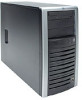
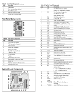
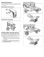
HP ProLiant ML110 Generation 2 Server Installation Sheet Read instructions completely before beginning installation procedure. © Copyright January 2005 Hewlett-Packard Development Company, L.P. The information contained herein is subject to change without notice. The only warranties for HP products and services are set forth in the express warranty statements accompanying such products and services. Nothing herein should be construed as constituting an additional warranty. HP shall not be liable for technical or editorial errors or omissions contained herein. Intel and Pentium are trademarks or registered trademarks of Intel Corporation or its subsidiaries in the United States and other countries. HP ProLiant ML110 Generation 2 Server Installation Sheet First Edition (January 2005) Part Number 375600-001 375600- 001 Configuring the Server 1. Connect all peripherals: - Keyboard - Mouse - Monitor NOTE: Refer to the HP ProLiant ML110 Generation 2 Server Support CD. Refer to the CD contents for additional information and updates not provided in this installation sheet. 2. Determine the server BIOS version: a. Power up the server. b. Press the Esc key at the HP logo screen, then press the Pause key to halt screen movement. c. Note the server BIOS version. d. Verify the server BIOS version against the latest BIOS version listed for this server on the HP website: http://www.hp.com e. If you do not have the latest BIOS, update the BIOS now. Refer to the HP ProLiant ML110 Generation 2 Server Maintenance and Service Guide available on the HP website: http://www.hp.com Default Boot Priority By default, the server searches for boot devices in the following order: 1. Removable device 2. IDE CD-ROM drive 3. Hard disk drive 4. PXE IBA GE slot 0A08 V1219 Identifying Server Components Front Panel Components Table 1: Front Panel Components Item Description 1 CD-ROM drive 2 CD-ROM drive mechanical eject hole 3 CD-ROM drive eject button 4 CD-ROM drive activity indicator 5 Full-height common bays 6 Dual-color status LED indicator • Green - Power indicator • Amber - System health indicator continued
-
 1
1 -
 2
2 -
 3
3 -
 4
4
 |
 |
