HP R12000/3 HP UPS R/T3000 Installation Instructions - Page 2
Tools and materials, Selecting a site, Readying the equipment, Installing the mounting rails - intl ups specifications
 |
View all HP R12000/3 manuals
Add to My Manuals
Save this manual to your list of manuals |
Page 2 highlights
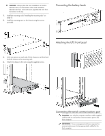
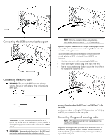
• Warranty information • Rails, with mounting hardware • Tower conversion stand (2) • Front mounting ears (2) and associated hardware • UPS • Front bezel • Mounting ear covers (2) (for rack installation only) • Communications port/option slot • REPO port connector block • Cord retention clips • Rear stabilization brackets (2) and associated hardware • The R/T3000h NA/JPN and R/T3000 INT models ship with: o Two 10 A, 1.83-meter (6-foot) IEC-to-IEC power cords (142263-001), for load equipment power o Two 10 A, 2.44-meter (8-foot) IEC-to-IEC power cords (142263-002), for load equipment power o Two 10 A, 3.05-meter (10-foot) IEC-to-IEC power cords (142263-003), for load equipment power o One 3.66-meter (12-foot) computer interface cable (397237-002) • The R/T3000 NA/JPN models ship with a nondetachable input power cord with an L5-30 plug and a 3.66-meter (12-foot) computer interface cable (397237-002). • The R/T3000h NA/JPN models ship with a nondetachable input power cord with an L6-20 plug and one C13 extension bar. • The R/T3000 INTL model has an IEC-20-C19 input power receptacle for a country-specific cord and one C13 extension bar. NOTE: All models ship with a computer interface cable. The computer interface cable is not needed for normal operation. To administer the UPS with power management software, connect the interface cable between the UPS communications port and the serial port on the host computer. Tools and materials The following tools are required for installation: • Phillips screwdriver • 10-mm hex-nut driver The following items are supplied with the rack: • Screws • Hex nuts • Cage nuts • Cage nut-fitting tool Selecting a site WARNING: To prevent fire or electric shock, install the unit in a temperature- and humidity-controlled indoor environment, free of conductive contaminants. When selecting a site, consider the following factors: • Elevated operating ambient temperature-If the equipment is installed in a closed or multi-unit rack assembly, the operating ambient temperature of the rack environment might be greater than room ambient temperature. Install the equipment in an environment compatible with the operating temperature. • Reduced air flow-In the rack, the rate of air flow required for safe operation of the equipment must not be compromised. • Circuit overloading-Consideration should be given to the connection of the equipment to the supply circuit and the effect that overloading of the circuits might have on overcurrent protection and supply wiring. Appropriate consideration of equipment nameplate ratings should be used when addressing this concern. • Reliable earthing-Reliable earthing of rack-mounted equipment should be maintained. Particular attention should be given to supply connections other than direct connections to the branch circuit, such as the use of power strips. • Electrical requirements-All models require a dedicated (unshared) branch circuit, suitably rated for the specific UPS as stated in "Input specifications" in the user guide. Readying the equipment 1. Check the battery recharge date specified on the label that is affixed to the shipping carton. IMPORTANT: Do not use the battery if the recharge date has passed. If the date on the battery recharge date label has passed without the battery being recharged, contact an HP authorized service representative for directions. 2. Transport the packaged unit to its installation location. 3. Unpack the equipment near the rack where the unit will be assembled. CAUTION: Always plan the rack installation so that the heaviest item is on the bottom of the rack. Install the heaviest item first, and continue to populate the rack from the bottom to the top. Installing the mounting rails WARNING: To reduce the risk of personal injury or damage to the equipment, be sure that: • The leveling feet are extended to the floor. • The full weight of the rack rests on the leveling feet. • The stabilizing feet are attached to the rack if it is a single-rack installation. • The racks are coupled together in multiple-rack installations. • Only one component is extended at a time. A rack may become unstable if more than one component is extended for any reason.
-
 1
1 -
 2
2 -
 3
3 -
 4
4 -
 5
5 -
 6
6 -
 7
7 -
 8
8
 |
 |
