HP Rp7410 User Guide, Third Edition - hp rp7405/rp7410 Servers - Page 66
Powering On the hp rp7405/rp7410 Server, Ctrl-B, Enter
 |
View all HP Rp7410 manuals
Add to My Manuals
Save this manual to your list of manuals |
Page 66 highlights
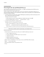
Installation Powering On the hp rp7405/rp7410 Server Powering On the hp rp7405/rp7410 Server After powering on the Management Processor (MP) (+3.3 V HKP), and checking that the MP detects the presence of the cell boards, power up the server. If using a LAN crossover cable with the laptop, review server activity for each partition configured, as it powers up and boots. Windows can be opened for the complex and for each partition. It is recommended that at least two windows be opened. • A window showing all activity in the complex. Following the installation procedure in this manual, will have a window open already on the laptop. To display activity for the complex: 1. If not already done, open a separate Reflection 1 window and connect to the MP. 2. From the MP Main Menu, select the VFP command with the s option. • A window showing activity for a single partition. To display activity for each partition as it powers up: 1. Open a separate Reflection 1 window and connect to the MP. 2. Select the VFP command and choose the partition desired to view. There should be no activity on the screen at this point in the installation process. NOTE More than one window cannot be opened using a serial display device. To power on the server: 1. Switch the power switch at the front of the server to On. The following events occur: • Power is applied to the server. • Processor Dependent Code (PDC) starts to run on each cell. • Cell self test executes. • Hardware initializes for the server. • Console communication is established. 2. When activity on the Reflection 1 screen stops, return to the MP Main Menu by typing Ctrl-B. 3. Enter co to enter console mode. 4. Enter the partition number of the partition to boot. 5. Press Enter. 44 Chapter 2
-
 1
1 -
2
-
3
-
4
-
5
-
6
-
7
-
8
-
9
-
10
-
11
-
12
-
13
-
14
-
15
-
16
-
17
-
18
-
19
-
20
-
21
-
22
-
23
-
24
-
25
-
26
-
27
-
28
-
29
-
30
-
31
-
32
-
33
-
34
-
35
-
36
-
37
-
38
-
39
-
40
-
41
-
42
-
43
-
44
-
45
-
46
-
47
-
48
-
49
-
50
-
51
-
52
-
53
-
54
-
55
-
56
-
57
-
58
-
59
-
60
-
 61
61 -
 62
62 -
 63
63 -
 64
64 -
 65
65 -
 66
66 -
 67
67 -
 68
68 -
 69
69 -
 70
70 -
 71
71 -
72
-
73
-
74
-
75
-
76
-
77
-
78
-
79
-
80
-
81
-
82
-
83
-
84
-
85
-
86
-
87
-
88
-
89
-
90
-
91
-
92
-
93
-
94
-
95
-
96
-
97
-
98
-
99
-
100
-
101
-
102
-
103
-
104
-
105
-
106
-
107
-
108
-
109
-
110
-
111
-
112
-
113
-
114
-
115
-
116
-
117
-
118
-
119
-
120
-
121
-
122
-
123
-
124
-
125
-
126
-
127
-
128
-
129
-
130
-
131
-
132
-
133
-
134
-
135
-
136
-
137
-
138
-
139
-
140
-
141
-
142
-
143
-
144
-
145
-
146
 |
 |