HP Scitex FB10000 Geffen TS Error 66048 - Page 3
Recommended Actions, Cross valves do not receive 24V supply
 |
View all HP Scitex FB10000 manuals
Add to My Manuals
Save this manual to your list of manuals |
Page 3 highlights
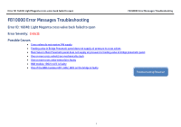
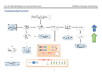
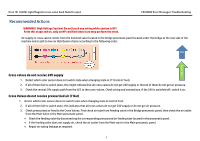
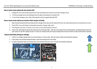
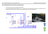
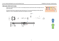
Error ID: 16048: Light Magenta cross valve back failed to open FB10000 Error Messages Troubleshooting Recommended Actions WARNING! High Voltage System! Do not touch any wiring while system is UP! From this stage and on, only an HP certified electrician may perform the tests. Air supply to cross valves comes from the Solenoid valve located in the bridge pneumatic panel located under the bridge at the rear side of the machine and is split to two air distribution chains according to the following order: Top Flowchart Cross valves do not receive 24V supply 1. Detect which color sensor does not switch state when changing state in CT (Control Tool). 2. If all of them fail to switch state, this might indicate that all cross valves do not get 24V supply or that all of them do not get air pressure. 3. Check the central 24V supply path from the LEC to the cross-valves. Check wiring and connections. If the 24V is switched off, switch it on. Cross Valves do not receive pressurized air (7 Bar) 1. Detect which color sensor does not switch state when changing state in Control Tool. 2. If all of them fail to switch state, this indicates that all cross valves do not get 24V supply or do not get air pressure. 3. Check pressurized air feed to the Cross Valves. First check air tube from Feeding valve in the Bridge pneumatic panel, then check the air outlet from the Main Valve in the Main pneumatic panel. • Check the feeding valve by disconnecting the corresponding pressurized air feeding tube located in the pneumatic panel. • If the feeding valve does not supply air, check the air outlet from the Main valve in the Main pneumatic panel. • Repair air tubing leakage as required. 3
-
 1
1 -
 2
2 -
 3
3 -
 4
4 -
 5
5 -
 6
6 -
 7
7
 |
 |
