HP Scitex FB950 HP Scitex FB950 - Site Preparation Guide Rev B - Page 6
Receiving the printer, Space requirements - used
 |
View all HP Scitex FB950 manuals
Add to My Manuals
Save this manual to your list of manuals |
Page 6 highlights
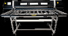
power to the printer is continuously within specifications. The UPS must be a 3-phase UPS capable of sourcing a minimum of 6000 VA, at a voltage in the range of 200-240 VAC, 50/60 Hz, and a maximum current rating of 16 Amps per phase. The UPS must have the proper plug and receptacle (see the Specifications below for details). Connect the UPS to the facility wall outlet, and connect the printer power cord to the UPS. Receiving the printer A fork lift truck with 114 cm (45 in) forks and a receiving dock are required to receive the printer from the shipper. Receiving the printer at ground level is not practical. The shipping crate is designed for fork lift handling: it can be pushed or pulled from the ends, or lifted from the sides as needed. After unpacking, dispose of the wood packaging according to local regulations. After unpacking, use the shipping casters to move the printer, or lift the printer with a fork lift at the marked lift points. CAUTION: Due to its physical dimensions and weight, the printer cannot be moved through building areas that cannot accommodate a fork lift, such as stairways or standard passenger elevators, or through doorways that are less than the width of the printer. Lifting the printer without a forklift could result in serious physical injury or death, and/or cause severe damage to the printer. Use the following dimensions and weights as you plan to receive and move the printer to its final location. Table 1 Shipping dimensions and weight Length 434.3 cm (171.0 in) Depth 160.0 cm (63.0 in) Height 181.6 cm (71.5 in) Weight 1122 kg (2473 lb) An Authorized Service Provider will install the printer. Depending on the space available at your location, you can either unpack and assemble the printer in your receiving area, then move the printer on its wheels to your production area, or move the shipping container unopened to your production area, and unpack and assemble it there. A technical representative will work with you in advance to plan for receiving, unpacking, and assembling the printer. The printer must be installed on a flat and stable floor that can safely support the weight of the printer, input and output tables, media, supplies, and operator. During installation, the printer and media tables will be leveled to ensure accurate media feeding. The printer and table feet can be adjusted to compensate for a maximum floor slope (elevation change) of 5.6 cm (2.2 in) over the printer width of 457 cm (180 in), and 5.1 cm (2.0 in) over the printer depth of 300 cm (118 in). Space requirements Allow enough space around all sides of the printer to load and unload ink and media, and operate the control panel. The rigid cut-sheet workflow requires some space planning for operator movement between the blank media stock (pallets or tables), the printer when loading media, operating the printer, and unloading media. Cut sheets are loaded from the input side of the printer. Locate the printer within 1.5 m (5 ft) from the service end, or 3.7 m (12 ft) from the user end, to the facility power outlet or power drop. The main and auxiliary power cords connect to inlets on the electronics box 2 Preparing for your new printer ENWW
-
 1
1 -
 2
2 -
 3
3 -
 4
4 -
 5
5 -
 6
6 -
 7
7 -
 8
8 -
 9
9 -
 10
10
 |
 |
