HP Server rp2400 Basic Cable Connections: Document Change List - HP rp2400 Ser - Page 1
HP Server rp2400 Manual
 |
View all HP Server rp2400 manuals
Add to My Manuals
Save this manual to your list of manuals |
Page 1 highlights
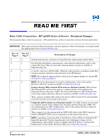
Basic Cable Connections - HP rp2400 Series of Servers - Document Changes The document Basic Cable Connections - HP rp2400 Series of Servers has been revised. See the table below. IMPORTANT The latest versions of these documents, and any updates to these documents, are posted under the appropriate server at http://docs.hp.com. Ver. 1.0 Page # 2 3 4 5 6 6 Ver. 2.0 Page # 2 7 8 9 10 10 Description of Change Send documentation comments to http://docs.hp.com/assistance/index.html. For detailed installation, maintenance, and technical information, refer to the rp24xx Hardware Manual and other documentation (search on rp2400) at http://docs.hp.com. 2. (Amber) Attention (ATTN) LED - When lit, indicates that a condition exists that requires operator attention and assistance from HP Support. NOTE: For technical support please call your local support hotline or contact HP at http://www.hp.com/support. NOTE: For more information on console configuration, refer to the rp24xx Hardware Manual (search on rp2400) at http://docs.hp.com. Using a Secure Web Console PCI card as a System Console. If the Secure Web Console PCI card is to be used as a system console, first configure the Guardian Service Processor (GSP). For more information on GSP configuration, refer to the rp24xx Hardware Manual (search on rp2400) at http://docs.hp.com. Then, connect an RJ45 LAN cable to the Secure Web Console PCI card installed in an I/O card slot on the back of the server. Using the LAN Console as a System Console. If a LAN Console is to be used as a system console, first configure the Guardian Service Processor (GSP). For more information on GSP configuration, refer to the rp24xx Hardware Manual (search on rp2400) at http://docs.hp.com. Then, connect it to the system with an RJ45 LAN cable to the RJ45 connector labeled 10BASE-T LAN Console connection on the back of the server. NOTE: [regarding connecting Power Distribution Units (PDUs) to Dedicated AC Input Receptacles] Current requirements vary with input voltage, server configuration, and number of power supplies installed. Refer to "System Site Preparation" in the rp24xx Hardware Manual at http://docs.hp.com. v1 Printed in the U.S.A. rp24xx_cable_change_list
-
 1
1
 |
 |