HP Spectre Ultrabook CTO 14t-3200 HP Spectre Ultrabook PC Maintenance and Serv - Page 50
Four Phillips PM2.0×4.0
 |
View all HP Spectre Ultrabook CTO 14t-3200 manuals
Add to My Manuals
Save this manual to your list of manuals |
Page 50 highlights
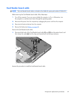
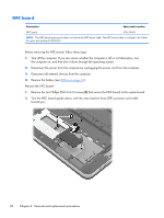
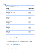
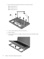
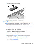
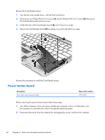
4. Remove the following screws that secure the top cover to the base enclosure: (2) Two Phillips PM2.0×5.5 (3) Five Phillips PM2.0×4.5 (4) Four Phillips PM2.0×4.0 5. Turn the computer right side up, with the front toward you. 6. Open the computer. 7. Lift the front edge of the top cover slightly, until the power button board and keyboard cables are accessible. 42 Chapter 4 Removal and replacement procedures
-
 1
1 -
2
-
3
-
4
-
5
-
6
-
7
-
8
-
9
-
10
-
11
-
12
-
13
-
14
-
15
-
16
-
17
-
18
-
19
-
20
-
21
-
22
-
23
-
24
-
25
-
26
-
27
-
28
-
29
-
30
-
31
-
32
-
33
-
34
-
35
-
36
-
37
-
38
-
39
-
40
-
41
-
42
-
43
-
44
-
 45
45 -
 46
46 -
 47
47 -
 48
48 -
 49
49 -
 50
50 -
 51
51 -
 52
52 -
 53
53 -
 54
54 -
 55
55 -
56
-
57
-
58
-
59
-
60
-
61
-
62
-
63
-
64
-
65
-
66
-
67
-
68
-
69
-
70
-
71
-
72
-
73
-
74
-
75
-
76
-
77
-
78
-
79
-
80
-
81
-
82
-
83
-
84
-
85
-
86
-
87
-
88
-
89
-
90
-
91
-
92
-
93
-
94
-
95
-
96
-
97
-
98
 |
 |
4.
Remove the following screws that secure the top cover to the base enclosure:
(2)
Two Phillips PM2.0×5.5
(3)
Five Phillips PM2.0×4.5
(4)
Four Phillips PM2.0×4.0
5.
Turn the computer right side up, with the front toward you.
6.
Open the computer.
7.
Lift the front edge of the top cover slightly, until the power button board and keyboard cables
are accessible.
42
Chapter 4
Removal and replacement procedures