HP Spectre XT TouchSmart 15-4100 HP SpectreXT TouchSmart Maintenance and Servi - Page 71
When replacing the system board, be sure that the following components are removed
 |
View all HP Spectre XT TouchSmart 15-4100 manuals
Add to My Manuals
Save this manual to your list of manuals |
Page 71 highlights
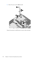
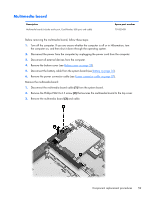
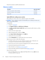
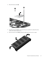
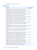
Description Spare part number Equipped with an Intel Dual Core i5-3317U 1.70-GHz processor (turbo up to 2.60-GHz), 1600MHz FSB, 3.00-MB L3 cache, 17 W, and the Windows 8 Professional operating system with trusted platform module security for use in all countries and regions except the People's Republic of China and Russia 700816-601 Equipped with an Intel Dual Core i5-3317U 1.70-GHz processor (turbo up to 2.60-GHz), 1600MHz FSB, 3.00-MB L3 cache, 17 W, and the Windows 8 Standard operating system with trusted platform module security for use in all countries and regions except the People's Republic of China and Russia 700816-501 Equipped with an Intel Dual Core i5-3317U 1.70-GHz processor (turbo up to 2.60-GHz), 1600MHz FSB, 3.00-MB L3 cache, 17 W, and the Windows 7 operating system with trusted platform module security for use in all countries and regions except the People's Republic of China and Russia 700816-001 Before removing the system board, follow these steps: 1. Turn off the computer. If you are unsure whether the computer is off or in Hibernation, turn the computer on, and then shut it down through the operating system. 2. Disconnect the power from the computer by unplugging the power cord from the computer. 3. Disconnect all external devices from the computer. 4. Remove the bottom cover (see Bottom cover on page 33). 5. Remove the battery (see Battery on page 35). 6. Remove the fan (see Fan on page 39). NOTE: When replacing the system board, be sure that the following components are removed from the defective system board and installed on the replacement system board: ● WLAN module (see WLAN module on page 37) ● Solid-state drive (see Solid-state drive on page 40) ● Memory module and shield (see Memory module on page 60) ● Heat sink (see Heat sink on page 65) ● RJ-45 jack cover (see RJ-45 jack cover on page 67) Component replacement procedures 63
-
 1
1 -
2
-
3
-
4
-
5
-
6
-
7
-
8
-
9
-
10
-
11
-
12
-
13
-
14
-
15
-
16
-
17
-
18
-
19
-
20
-
21
-
22
-
23
-
24
-
25
-
26
-
27
-
28
-
29
-
30
-
31
-
32
-
33
-
34
-
35
-
36
-
37
-
38
-
39
-
40
-
41
-
42
-
43
-
44
-
45
-
46
-
47
-
48
-
49
-
50
-
51
-
52
-
53
-
54
-
55
-
56
-
57
-
58
-
59
-
60
-
61
-
62
-
63
-
64
-
65
-
 66
66 -
 67
67 -
 68
68 -
 69
69 -
 70
70 -
 71
71 -
 72
72 -
 73
73 -
 74
74 -
 75
75 -
 76
76 -
77
-
78
-
79
-
80
-
81
-
82
-
83
-
84
-
85
-
86
-
87
-
88
-
89
-
90
-
91
-
92
-
93
-
94
-
95
-
96
-
97
-
98
-
99
-
100
-
101
 |
 |
