HP StorageWorks 30 HP StorageWorks Disk Enclosure Power Supply/Blower Replacem - Page 2
Removing a blower, Installing a blower, Removing a power supply
 |
View all HP StorageWorks 30 manuals
Add to My Manuals
Save this manual to your list of manuals |
Page 2 highlights
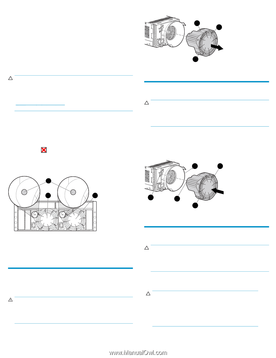
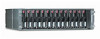
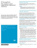
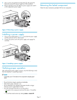
• On the front of the MSA1000, use the controller display buttons to scroll through the messages displayed on the controller LCD panel and locate the following message: 409 STORAGE BOX # POWER SUPPLY FAILED The value in the message identifies which enclosure has the failed power supply. • Box 1: MSA enclosure • Box 2: Disk enclosure attached to Port A of the MSA • Box 3: Disk enclosure attached to Port B of the MSA EVA products CAUTION: If HP Command View EVA does not present a status consistent with the power supply/blower status indicator, or if either HP Command View EVA or your system monitoring tool indicates multiple hardware failures, contact HP support for assistance (http://www.hp.com/support). • Analyze any failure messages received. • Check status using HP Command View EVA: 1. In the Navigation pane, select Storage system > Hardware > Rack > Disk enclosure. 2. In the Content pane, select the Power tab or the Cooling tab then the appropriate component (1 or 2). The Operational state should be Failed. 3. To help identify the correct enclosure, click Locate > Locate On to flash the status indicators on the front of the disk enclosure. • Check the power supply/blower status indicator (Figure 1). It should be off. 1 2 1 1 0007a Figure 2 Removing a blower Installing a blower CAUTION: Pressing on the center section of the blower can damage the blades or the housing. Only press on the outer edge of the blower when installing it. 1. Align the blower guide post (2, Figure 3) with the mounting hole next to the power supply connector (1). 2. Slide the blower onto the power supply (4) until the mounting tabs (3) snap into place. 4 3 2 3 1 2 3 0008a Figure 3 Installing a blower 0006b 1. Status indicator 3. Power supply/blower 2 2. Power supply/blower 1 Figure 1 Power supply/blower status indicator Removing a blower It is not necessary to remove the power supply to replace a failed blower. WARNING! The blower motor does not stop immediately when the blower is removed. Keep your fingers away from the blower blades until the motor stops. Removing a power supply CAUTION: When a power supply is removed, the enclosure could shut down due to overheating within seven minutes unless the power supply is replaced. 1. Disengage the power cord lock (1, Figure 4) and disconnect the power cord from the power supply. CAUTION: When removing the left power supply, ensure the cord lock on the right power supply is engaged. This will avoid inadvertently disconnecting the right power supply. Also take care to avoid disrupting the cables on the I/O module to left of the power supply. While pushing in on the two wine-colored mounting tabs (1, Figure 2), pull the blower (2) away from the power supply. Page 2
-
 1
1 -
 2
2 -
 3
3
 |
 |