HP StorageWorks 4/16 HP StorageWorks DC and DC04 SAN Backbone Director Switche - Page 139
Port numbering, Managing cables, Table 30, Port numbering templates,
 |
View all HP StorageWorks 4/16 manuals
Add to My Manuals
Save this manual to your list of manuals |
Page 139 highlights
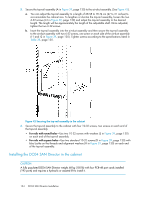
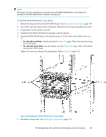
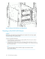
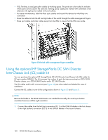
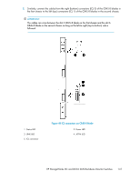
3. Turn the AC power switches on the power supplies to ON (I). The AC power switches light green when switched on and power is supplied. 4. The DC04 SAN Director performs a Power-on Self-Test (POST) each time it is powered on. POST takes approximately 10 minutes and is complete when the indicator light activity indicates the operational state. For information about LED patterns, see Table 30 on page 159. You can bypass POST by using the fastBoot command. You can also disable POST for successive reboots on the DC04 SAN Director using the diagDisablePost command. NOTE: To prevent a potential IP address conflict, do not connect the DC04 SAN Director to the network until the IP addresses are configured. See "Configuring IP addresses" on page 147. Port numbering The DC04 SAN Director uses the following port numbering method (see "Port numbering templates" on page 239). IMPORTANT: Slots are numbered 1 through 8, from bottom to top. Control processor blades (CP8) can be installed only in slots 4 and 5. Core switch blades (CR4S-8) can be installed only in slots 3 and 6. • FC8-16 port blade-Ports are numbered from 0 through 15 from left to right. • FC8-32 port blade-Ports are numbered from 0 through 15 from left to right on the bottom set of ports and 16 through 31 from left to right on the top set of ports. • FC8-48 port blade-Ports are numbered from 0 through 23 from left to right on the bottom set of ports and 24 through 47 from bottom to top on the top set of ports. • FC10-6 port blade-Ports are numbered from 0 through 5 from left to right. • FR4-18i router blade-The sixteen physical FC ports on this blade are numbered 0 through 15 from left to right. The two GbE ports are numbered from the bottom as Ge0 and Ge1. These ports, when fully configured, enable sixteen VE_Ports or VEX _Ports and appear in the switchShow command as ports 16 through 31. Managing cables NOTE: The minimum bend radius for a 50 micron cable is 2 in. under full tensile load and 1.2 in. with no tensile load. A pair of vertical cable management finger assemblies provide routing paths to prevent cables from hanging down in front of other blades. See Figure 48. Follow these cabling recommendations: • Leave at least 1 m (3.28 ft) of slack for each port cable. This provides room to remove and replace the switch. HP StorageWorks DC and DC04 SAN Backbone Director Switches 139
-
 1
1 -
2
-
3
-
4
-
5
-
6
-
7
-
8
-
9
-
10
-
11
-
12
-
13
-
14
-
15
-
16
-
17
-
18
-
19
-
20
-
21
-
22
-
23
-
24
-
25
-
26
-
27
-
28
-
29
-
30
-
31
-
32
-
33
-
34
-
35
-
36
-
37
-
38
-
39
-
40
-
41
-
42
-
43
-
44
-
45
-
46
-
47
-
48
-
49
-
50
-
51
-
52
-
53
-
54
-
55
-
56
-
57
-
58
-
59
-
60
-
61
-
62
-
63
-
64
-
65
-
66
-
67
-
68
-
69
-
70
-
71
-
72
-
73
-
74
-
75
-
76
-
77
-
78
-
79
-
80
-
81
-
82
-
83
-
84
-
85
-
86
-
87
-
88
-
89
-
90
-
91
-
92
-
93
-
94
-
95
-
96
-
97
-
98
-
99
-
100
-
101
-
102
-
103
-
104
-
105
-
106
-
107
-
108
-
109
-
110
-
111
-
112
-
113
-
114
-
115
-
116
-
117
-
118
-
119
-
120
-
121
-
122
-
123
-
124
-
125
-
126
-
127
-
128
-
129
-
130
-
131
-
132
-
133
-
 134
134 -
 135
135 -
 136
136 -
 137
137 -
 138
138 -
 139
139 -
 140
140 -
 141
141 -
 142
142 -
 143
143 -
 144
144 -
145
-
146
-
147
-
148
-
149
-
150
-
151
-
152
-
153
-
154
-
155
-
156
-
157
-
158
-
159
-
160
-
161
-
162
-
163
-
164
-
165
-
166
-
167
-
168
-
169
-
170
-
171
-
172
-
173
-
174
-
175
-
176
-
177
-
178
-
179
-
180
-
181
-
182
-
183
-
184
-
185
-
186
-
187
-
188
-
189
-
190
-
191
-
192
-
193
-
194
-
195
-
196
-
197
-
198
-
199
-
200
-
201
-
202
-
203
-
204
-
205
-
206
-
207
-
208
-
209
-
210
-
211
-
212
-
213
-
214
-
215
-
216
-
217
-
218
-
219
-
220
-
221
-
222
-
223
-
224
-
225
-
226
-
227
-
228
-
229
-
230
-
231
-
232
-
233
-
234
-
235
-
236
-
237
-
238
-
239
-
240
-
241
-
242
-
243
-
244
-
245
-
246
-
247
-
248
-
249
-
250
-
251
-
252
-
253
-
254
-
255
-
256
 |
 |
