HP StorageWorks MSA1000 HP StorageWorks 2/8q Fibre Channel Switch V.1 Installa - Page 2
Step 3: Mount the switch, Step 4: Install the SFPs, Step 5: Connect the cables, Step 6: Con - user guide
 |
View all HP StorageWorks MSA1000 manuals
Add to My Manuals
Save this manual to your list of manuals |
Page 2 highlights
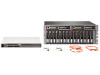
Step 3: Mount the switch For a surface mount: Obtain the rubber feet from the switch carton and attach the feet to the bottom of the switch. Then, place the switch on a stable work surface. For a rack mount: Note: This switch is mounted from the rear of the rack. 1. Obtain the 2U rack template and 2U rail kit from the MSA1000 SAN Kit carton, and the switch mounting adapter brackets and screws from the switch carton. 2. Use the template to mark the holes on the front and back of the rack, to indicate the location for the rails. 3. From the rear of the rack, install the rails by inserting the left rail (marked L) into the inside-left rear of the rack, until the pins extend through the holes marked in step 2 and the scissor-type locking latch engages. Then, extend the other end of the rail toward the inside front of the rack until the pins extend through the marked holes. Loosen the locking nut on the retaining bracket and slide the bracket to the farthest position near the front of rack. Repeat these steps to install the other rail. 4. Fasten the mounting adapter brackets to the switch, with the port side of the switch facing the flanges of the adapter brackets. Position the brackets so that the switch is set back approximately 3 inches from the flanges. 5. From the rear of the rack, slide the switch assembly onto the previously installed rails, until the flanges of the mounting brackets are flush with the rear uprights of the rack. 6. Secure the switch to the rack by securing the provided screws through the flanges to the rear of the rack, and then, from the front of the rack, slide the retaining brackets on the rail towards the switch, until they engage the switch. Then tighten the thumbscrews on the retaining bracket. Step 4: Install the SFPs 1. Obtain the SFPs. Four SFPs are included in the switch shipping carton; additional SFPs may be purchased separately. 2. Insert an SFP into a Fibre Channel port. Push the SFP into the port with gentle pressure until the SFP snaps into place. Note: An SFP fits only one way in the Fibre Channel port. If the SFP does not install under gentle pressure, pull it out of the port, turn it over, and re-insert it. Step 5: Connect the cables 1. Connect a Fibre Channel cable between each SFP installed in the switch and its corresponding device. 2. Attach the power cable between the switch and the power source. - Verify that the Input Power LED (green) is illuminated. - Wait a few minutes for the self test to complete. - Verify that the Heartbeat LED is blinking (once per second) and the System Fault LED (amber) is NOT illuminated. Physical installation of your new switch is complete. Step 6: Configure the switch The 2/8q FC Switch, the HBA in the server, and the storage in the MSA are configured using tools provided in the MSA1000 Small Business SAN Kit carton. Obtain the MSA1000 Small Business SAN Kit Installation Instructions from the MSA1000 SAN Kit carton, and follow the instructions on the poster to prepare and configure the devices. For additional information about your 2/8q FC Switch, refer to the switch documents provided on the MSA1000 SAN Kit Documentation CD, including the Installation Guide, Management User Guide, Release Notes, and Readme information. Page 2
-
 1
1 -
 2
2
 |
 |
