HP StorageWorks Modular Smart Array 1000 HP StorageWorks SFP Transceiver Repla - Page 2
Step 1: Removing the SFP transceiver, Verifying the replacement, Returning the failed component
 |
View all HP StorageWorks Modular Smart Array 1000 manuals
Add to My Manuals
Save this manual to your list of manuals |
Page 2 highlights
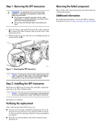
Step 1: Removing the SFP transceiver WARNING: To reduce the risk of injury from laser radiation or damage to the equipment, observe the following precautions: ■ Do not open any panels, operate controls, make adjustments, or perform procedures to a laser device other than those specified herein. ■ Do not stare into the laser beam when panels are open. 1. Press the release clip on the bottom of the cable connector 1 to remove the Fibre Channel cable from the back of the failed transceiver. 2. Pull the transceiver out of the device by pulling up and out on the plastic tab 2. Returning the failed component Please follow the return instructions provided in the new component package. Additional information For additional information, refer to the MSA technical documents web site at http://www.hp.com/go/msa1000. 2 1 15094 Figure 1: Removing the SFP transceiver Caution: Touching the end of a fibre cable damages the cable. Whenever a fibre cable is not connected, replace the protective covers on the ends of the cables. Step 2: Installing the SFP transceiver Insert the new SFP transceiver into the controller component and replace the Fibre Channel cable. Caution: To reduce the risk of damage to the equipment, do not use excessive force when inserting the transceiver. Installation is complete. Verifying the replacement After replacing the failed SFP transceiver: ■ No new error messages should be displayed on the LCD. Unread error log messages may cause the LED to remain lit. Be sure all error messages that have been responded to are deleted. ■ Both the 1G and 2G LEDs on the Fibre Channel board should be lit.
-
 1
1 -
 2
2
 |
 |
