| Section |
Page |
| hp surestore director fc-64 User’s Guide |
3 |
| Notice |
4 |
| Warranty |
4 |
| Safety Instructions |
4 |
| Format Conventions |
4 |
| 1 hp surestore director fc-64 Operating Features |
5 |
| 2 Operating the Director |
6 |
| 3 Product Manager Overview |
6 |
| 4 Monitoring and Managing the Director |
7 |
| 5 Configuring the Director |
8 |
| 6 Director Logs |
9 |
| 7 Using Maintenance Features |
9 |
| Using SNMP to Manage the Director |
9 |
| Product Manager Messages |
10 |
| FPM Card Maps |
11 |
| Regulatory Statements |
11 |
| INDEX |
11 |
| 1 hp surestore director fc-64 Operating Features |
19 |
| Figure 1 Rack-Mount hp surestore director FC-64s and Server |
20 |
| Figure 2 hp surestore director fc-64 through Server, SNMP Management Stations, and Remote User Wo... |
21 |
| Figure 3 Director FRUs. Front Access |
22 |
| Figure 4 Director FRUs, Rear Access (RFI Shield Removed) |
23 |
| Figure 5 HP EFC Server |
28 |
| Figure 6 Ethernet Hub |
30 |
| Figure 7 Out-of-Band Director Management |
38 |
| 1. The current version of firmware is retained in nonvolatile memory while the new firmware loads... |
45 |
| 2. The backup CTP card performs an IPL with the new firmware. |
45 |
| 3. The backup CTP card then becomes the master CTP card, and the old master card becomes the new ... |
45 |
| 4. The new master card then loads the firmware to the new backup CTP card. |
45 |
| 5. Upon successful completion, the new firmware image becomes the master version and the previous... |
45 |
| Port Diagnostics |
48 |
| Figure 8 Example of a Multiswitch Fabric |
51 |
| 1. Define the FC-64s through the New Product dialog box in the HP EFC Manager. |
52 |
| 2. Make sure that the directors that you are joining are powered off. |
52 |
| 3. Connect the directors through fiber cables attached to dedicated fiber optic ports on the FC-6... |
52 |
| 4. Power the directors back on. |
52 |
| 5. Place the cursor over the View icon in the HP EFC Manager and select Fabric. |
52 |
| 6. The Fabric View displays. |
52 |
| 7. Click on the fabric icon in the Fabric View to display the Fabric Manager window. The Fabric V... |
53 |
| Principal Switch Selection |
53 |
| Fabric WWN Assignment |
54 |
| Domain ID Assignment |
54 |
| Path Selection |
55 |
| Frame Delivery Order |
56 |
| Rerouting Delay |
56 |
| E_Port Segmentation |
56 |
| Fabric Services and State Change Notifications |
57 |
| Zoning Configurations for Joined Fabrics |
58 |
| Port Numbering |
58 |
| Nodes |
58 |
| Node and Director WWN |
58 |
| 2 Operating the Director |
61 |
| 1. One alternating current (AC) power cord is required for each power supply installed. These are... |
62 |
| 2. At the bottom rear of the director, set the power switch (circuit breaker) to the up position.... |
62 |
| a. Amber LEDs on both CTP cards and all fiber port module (FPM) cards illuminate momentarily. |
62 |
| b. The green LED on each CTP card (active and backup) illuminates as the card is tested and FPM c... |
62 |
| c. Green LEDs associated with Fibre Channel ports sequentially illuminate as the ports are tested. |
62 |
| Figure 9 AC Power Switch Location |
63 |
| 3. After successful POST completion, the green power LED on the front bezel, green LED on the act... |
63 |
| 4. If a POST error or other malfunction occurs, go to MAP 000: Start MAP in the Diagnostics chapt... |
63 |
| Notes |
64 |
| Procedure |
64 |
| 1. Notify the customer the director will be powered off. Ensure the customer’s system administrat... |
64 |
| 2. Set the director offline. For instructions, refer to Set Online State on page 203 and return h... |
64 |
| 3. At the bottom rear of the director, set the power switch (circuit breaker) to the down positio... |
64 |
| 4. If servicing the director, disconnect power cord(s) from the input power module at the bottom ... |
64 |
| Figure 10 Front Access - FRUs and Indicators |
65 |
| Power and Error Indicators |
65 |
| FPM Cards and Fibre Channel Ports |
66 |
| Figure 11 FPM Card Indicators and Connectors |
67 |
| CTP Cards |
68 |
| Figure 12 CTP Card Indicators, Connectors, and Controls |
68 |
| LED Indicators |
68 |
| IML Button |
69 |
| Ethernet Connector |
69 |
| Power Supplies |
69 |
| Figure 13 Power Supply Indicators |
70 |
| Figure 14 Rear Access - FRUs, Indicators, Connectors, and Controls |
71 |
| Fan Modules |
71 |
| Serial Crossbar (SBARs) Cards |
71 |
| Input Power Module |
71 |
| AC Power Connectors |
72 |
| Power On/Off Switch |
72 |
| Maintenance Port |
72 |
| 1. Ensure that no active remote sessions are in progress through the Session View. To open the Se... |
73 |
| 2. Close the Product Manager and exit the HP EFC Manager applications if they are active. |
73 |
| 3. Click the Windows Start button at the lower left corner of the desktop, then click the Shut Do... |
73 |
| 4. When the Shut Down Windows dialog box displays, select Shut down the computer. |
73 |
| 5. Click the Yes button to shut down the HP EFC Server. |
73 |
| 6. Wait until the message “It’s now safe to turn off your computer” displays, and then press the ... |
73 |
| 3 Product Manager Overview |
75 |
| Figure 15 HP EFC Server and Remote Workstation Configuration (Dual Ethernet) |
78 |
| Figure 16 Typical Dialog Box |
79 |
| Keyboard Navigation |
80 |
| 1. Perform one of the following steps: |
81 |
| 2. Perform one of the following steps if you are using a remote user workstation (a network PC wi... |
81 |
| Figure 17 HP EFC Manager Icon |
81 |
| 3. When the HP EFC Manager login screen displays, enter your user name and password. The default ... |
81 |
| 4. In the HP EFC Server box on the login screen select the HP EFC Server to which you wish to con... |
82 |
| 5. Click Activate or press the <Enter> key on your keyboard. |
82 |
| Figure 18 Main HP EFC Manager Window |
82 |
| Figure 19 FC-64 Icon |
83 |
| Figure 20 FC-64 Product Manager Window |
84 |
| Title Panel |
85 |
| Navigation Control Panel |
85 |
| View |
85 |
| Configure |
87 |
| Logs |
90 |
| Maintenance |
91 |
| Help |
93 |
| Close |
94 |
| Alert Panel |
94 |
| Main Panel |
95 |
| Table 1 Operating Status - Alert Panel and Director Status� |
95 |
| Hardware View |
96 |
| Figure 21 Hardware View |
97 |
| Director Menu |
98 |
| FPM Card Menu |
98 |
| CTP Card Menu |
99 |
| Cooling Fan Module Menu |
99 |
| SBAR Card Menu |
99 |
| Port Card View |
99 |
| Figure 22 Port Card View |
100 |
| Port List View |
101 |
| Figure 23 Port List View |
102 |
| FRU List View |
103 |
| Figure 24 FRU List View |
104 |
| Node List View |
104 |
| Figure 25 Node List View |
105 |
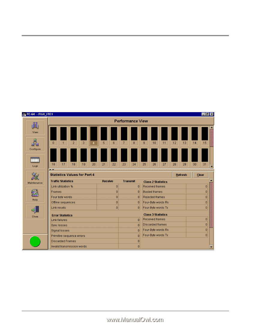
| Performance View |
106 |
| Figure 26 Performance View |
107 |
| 1. Select the Close icon from the Close menu on the navigation control panel. |
108 |
| 2. To log out or exit the HP EFC Manager, place the cursor over the Logout/Exit icon. Select eith... |
108 |
| User Rights for Specific Functions |
109 |
| Table 2 User Rights for Product Manager (cont’d) |
110 |
| Figure 27 QuikSync Icon in Windows System Tray |
113 |
| Enabling QuikSync |
114 |
| 1. Click the Windows Start button and select Programs, then Iomega QuikSync-> QuikSync. |
114 |
| Figure 28 Iomega QuikSync Dialog Box |
114 |
| 2. Click On to enable QuikSync |
114 |
| 3. Click OK. |
114 |
| QuikSync Settings |
114 |
| 1. Open the QuikSync dialog box using one of these steps. |
115 |
| 2. Verify that the dialog box is configured exactly as it displays in Figure 28. |
115 |
| 3. Click the Advanced tab. The following displays: |
115 |
| Figure 29 Iomega QuikSync Dialog Box (Advanced Tab) |
115 |
| 4. Verify that the dialog box is configured exactly as it displays in Figure 29. |
116 |
| 5. Click OK. |
116 |
| 4 Monitoring and Managing the Director |
117 |
| Status Table |
119 |
| Status |
119 |
| State |
119 |
| No Link Status |
119 |
| Alert Panel Status Indicator |
121 |
| FRUs |
121 |
| Figure 30 Monitoring Hardware Operation - FC-64 Hardware View |
122 |
| 1. FPM card attention indicator: |
122 |
| 2. FPM card failure indicator: |
123 |
| 3. CTP card failure indicator: |
123 |
| 4. Active CTP card indicator: |
123 |
| 5. Power, system error, and unit beaconing indicators: |
123 |
| 6. Power supply failure indicator: |
124 |
| 7. Cooling fan module failure indicator: |
124 |
| 8. SBAR card beaconing indicator: |
124 |
| 9. SBAR failure indicator: |
124 |
| Displaying FRU Information |
125 |
| Figure 31 FRU Properties Dialog Box |
125 |
| Figure 32 FPM Card FRU Properties Dialog Box |
126 |
| Displaying Director Information |
126 |
| Figure 33 Director Properties Dialog Box |
126 |
| Director Menu |
127 |
| 1. Click to display the Configure Date and Time dialog box. |
128 |
| Figure 34 Configure Date and Time Periodic Synchronization Dialog Box |
129 |
| 2. Perform one of the following steps: |
129 |
| Figure 35 Configure Date and Time Manually |
130 |
| 1. Click the Set Offline or Set Online button to toggle between offline and online states. |
130 |
| Figure 36 Set Online State Dialog Box (Director is Online) |
130 |
| Figure 37 Set Online State Dialog Box (Director is Offline) |
131 |
| 2. When the Set Online or Set Offline warning dialog box displays, click OK to set the director o... |
131 |
| FPM Card Menu |
131 |
| Port Menu |
132 |
| CTP Card Menu |
132 |
| Figure 38 Switchover CTP Dialog box |
133 |
| Fan Module Menu |
133 |
| SBAR Card Menu |
134 |
| Symbols and Indicators |
135 |
| Figure 39 Port Card View |
135 |
| 1. The amber indicator at the top of a FPM card illuminates when the FPM card fails. An FPM card ... |
136 |
| 2. In Figure 39, the amber LED is blinking (while the green LED is on) for the first port on the ... |
136 |
| 3. When the port is operational but not communicating with an attached device, the green indicato... |
136 |
| 4. If the port fails, the amber indicator for port illuminates and a blinking red and yellow diam... |
136 |
| 5. A yellow triangle (attention indicator) displays next to a port connector for a variety of rea... |
136 |
| 6. The Port Card View indicates a failed port by a blinking red and yellow diamond alert symbol b... |
137 |
| Displaying Port Information |
137 |
| Figure 40 Port Properties Dialog Box |
137 |
| Port Card Menu |
140 |
| Port Menu |
140 |
| Figure 41 Port List View |
143 |
| Figure 42 FRU List View |
147 |
| Figure 43 Node List View |
149 |
| Figure 44 Node Properties Dialog Box |
152 |
| Figure 45 Performance View |
154 |
| Statistics Description |
156 |
| Traffic Statistics with Receive and Transmit Values |
156 |
| Class 2 Statistics |
157 |
| Class 3 Statistics |
157 |
| Error Statistics |
158 |
| Table 3 Port States and Indicators (cont’d) |
160 |
| 5 Configuring the Director |
165 |
| 1. Place the cursor over the Configure icon and select Identification. |
166 |
| Figure 46 Configure Identification Dialog Box |
166 |
| 2. Click in the name field and enter a name for the director. The name could reflect the director... |
166 |
| 3. Click in the description field and enter a description of the director. |
167 |
| 4. Click in the location field and enter the location of the director. |
167 |
| 5. Click in the contact field and enter appropriate information about a contact person, such as a... |
167 |
| 6. Click Activate to save the data and close the dialog box. |
167 |
| 7. If you are finished configuring the director, back up the configuration data. For more informa... |
167 |
| 1. If the director is not offline: |
168 |
| a. Place the cursor over the Maintenance icon and select Set Online State. |
168 |
| Figure 47 Set Online State Dialog Box (Currently Online) |
168 |
| b. Click the Set Offline button to set the director offline. |
168 |
| 2. Place the cursor over the Configure icon and select the Operating Mode option. |
168 |
| Figure 48 Configure Operating Mode Dialog Box |
168 |
| 3. Select either open systems or S/390 mode. |
169 |
| Figure 49 Configuring Interoperability Mode (Open Systems Mode) |
169 |
| 4. Click Activate to save your changes and to close the dialog box. |
169 |
| 5. Set the director online: |
169 |
| a. Place the cursor over the Maintenance icon and select Set Online State. |
169 |
| b. When the Set Online State dialog box displays, click the Set Online button to set the director... |
169 |
| 1. Configure the director offline. |
172 |
| a. Place the cursor over the Maintenance icon and select Set Online State. |
172 |
| Figure 50 Set Online State Dialog Box (Currently Online) |
173 |
| b. Click the Set Offline button to set the director offline as shown in Figure 50. |
173 |
| 2. Place the cursor over the Configure icon and select Operating Parameters. |
173 |
| Figure 51 Configure Operating Parameters Dialog Box |
173 |
| 3. Enter data into dialog box fields as follows. |
173 |
| 4. Click the Activate button to save the configuration and close the dialog box. |
174 |
| 5. Set the director online. |
174 |
| a. Place the cursor over the Maintenance icon and select Set Online State. |
174 |
| b. When the Set Online State dialog box displays, click the Set Online button to set the director... |
174 |
| 6. Back up the configuration data when you are finished configuring the director. For more inform... |
174 |
| 1. Place the cursor over the Configure icon and select Ports. |
177 |
| Figure 52 Configure Ports Dialog Box (Open Systems Mode) |
178 |
| 2. Click a Name field and type a name that reflects the end device connected through the port. Fo... |
178 |
| 3. Block or unblock operation for a port by clicking the check box in the Blocked column. When a ... |
178 |
| 4. Enable or disable extended distance buffering for the port by clicking the check box in the 10... |
178 |
| 5. Enable or disable LIN alerts for the port by clicking the check box in the LIN Alerts column. ... |
178 |
| 6. Select a port type by clicking in the Type field and selecting from the list. |
179 |
| 7. Use the scroll bar on the right side of the Configure Ports dialog box table to display additi... |
179 |
| 8. Activate changes and close the dialog box by clicking the Activate button. |
179 |
| 9. If you are finished configuring the switch, back up the configuration data. For more informati... |
179 |
| 1. Place the cursor over the Configure icon and select Ports. |
179 |
| Figure 53 Configure Ports Dialog Box (S/390 Mode) |
180 |
| 2. Enable or disable extended distance buffering for the port by clicking the check box in the 10... |
180 |
| 3. Enable or disable LIN alerts for the port by clicking the check box in the LIN Alerts column. ... |
180 |
| 4. Use the scroll bar on the right side of the Configure Ports dialog box table to display additi... |
180 |
| 5. Activate changes and close the dialog box by clicking Activate. |
180 |
| 6. If you are finished configuring the switch, back up the configuration data. For more informati... |
180 |
| Figure 54 Prohibited Port Connection Symbol |
182 |
| Procedure |
183 |
| 1. Place the cursor over the Configure icon and select Addresses, then select Active. |
183 |
| Figure 55 Configure Addresses - Active Dialog Box |
184 |
| 2. Enter information into the appropriate fields. |
184 |
| 3. Click the squares to either prohibit or allow connections. In Figure 55, port address 07 is pr... |
184 |
| 4. Click Save As to open the Save Address Configuration As dialog box. |
184 |
| 5. Click the Port Name field and enter a name. |
184 |
| 6. Click OK to save changes and to close the Save Address Configuration As dialog box. |
185 |
| 7. In the Configure Addresses - Active dialog box, click Activate to activate the configuration o... |
185 |
| Procedure |
185 |
| 1. Place the cursor over the Configure icon and select Addresses, then select Stored. |
185 |
| Figure 56 Address Configuration Library Dialog Box |
185 |
| 2. Select a configuration entry by clicking on the row. Then use one of the procedures below. |
185 |
| 3. When finished managing the library, click Close to close the dialog box. |
186 |
| 1. Place the cursor over the Configure icon and select SNMP. |
187 |
| Figure 57 Configure SNMP Dialog Box |
188 |
| 2. Click the Enable Authorization Traps field to enable authorization traps to be sent to SNMP ma... |
188 |
| 3. Click a field in the Community Name column to select the row. Enter the SNMP community name fo... |
188 |
| 4. Click the Write Authorization check box to enable write authorization for the community name. ... |
188 |
| 5. Enter the IP address for a trap recipient (SNMP management station) by clicking in the Trap Re... |
188 |
| 6. Click the Advanced button if you wish to override the default user datagram protocol (UDP) tra... |
188 |
| 7. Enter UDP port numbers in the UDP Port Number column. You can override the default UDP port nu... |
189 |
| Figure 58 Configure SNMP Dialog Box |
189 |
| 8. Click Activate to activate the data and close the dialog box. |
189 |
| 9. If you are finished configuring the director, back up the configuration data. For more informa... |
189 |
| 1. Place the cursor over the Configure icon and select Management Server. |
190 |
| Figure 59 Configure Open Systems Management Server Dialog Box |
190 |
| 2. Click the check box in the Host Control Prohibited field to display a check mark and allow wri... |
190 |
| 3. Activate changes and close the dialog box by clicking Activate. |
190 |
| 4. If you are finished configuring the director, you can back up the configuration data. For more... |
190 |
| 1. Set the director offline using the Set Online State dialog box. For help, refer to Set Online ... |
191 |
| 2. Place the cursor over the Configure icon and select Features. |
191 |
| Figure 60 Configure Feature Key Dialog Box |
191 |
| 3. Click New to add a new feature key. |
192 |
| Figure 61 New Feature Key Dialog Box |
192 |
| 4. Enter the director’s feature key and click OK. |
192 |
| Figure 62 Enable Feature Key Dialog Box |
193 |
| 5. Click Activate to activate the new feature key. |
193 |
| 6. Set the director back online. |
193 |
| 7. When you are finished configuring the director, you can back up the configuration data. For mo... |
193 |
| 1. Place the cursor over the Configure icon and select Date/Time. |
194 |
| Figure 63 Configure Date and Time Periodic Synchronization Dialog Box |
194 |
| 2. Perform one of the following steps: |
195 |
| a. Make sure that Periodic Date/Time Synchronization is disabled (no check). Refer to Figure 64. |
195 |
| Figure 64 Configure Date and Time Manually |
195 |
| b. Click in a Date or Time field that you want to change. |
195 |
| c. Delete characters and enter new ones as required or highlight the existing character by draggi... |
195 |
| d. Click Activate to set the date and time on the director. |
196 |
| 3. If you are finished configuring the director, back up the configuration data. For more informa... |
196 |
| 1. Place the cursor over the Configure icon and select Export Configuration Report. |
197 |
| Figure 65 Export Configuration Dialog Box |
198 |
| 2. Select the folder where you want to save the file. |
198 |
| 3. Type in a file name and extension in the File name field. |
198 |
| 4. Click Save. |
198 |
| 7 Using Maintenance Features |
201 |
| Procedure |
202 |
| 1. Place the cursor over the Maintenance icon and select Swap Ports. |
202 |
| Figure 71 Swap Ports Dialog Box |
202 |
| 2. Enter the first address (in hexadecimal format). |
202 |
| 3. If you want to unblock the port, click Unblock after swap. Note that ports are automatically b... |
203 |
| 4. Enter the second address (in hexadecimal format). |
203 |
| 5. If you want to unblock the port, click Unblock after swap. |
203 |
| 6. Click Next to continue. |
203 |
| 7. Follow the on-screen instructions and click Next to continue through to the next screen. |
203 |
| 8. If you are finished configuring the director, back up the configuration data. For more informa... |
203 |
| 1. Place the cursor over the Maintenance icon and select IPL. |
205 |
| Figure 72 IPL Confirmation Dialog Box |
205 |
| 2. Click Yes. |
205 |
| 1. Place the cursor over the Maintenance icon and select Set Online State. |
207 |
| Figure 73 Set Online State Dialog Box (State Is Offline) |
207 |
| Figure 74 Set Online State Dialog Box (State Is Online) |
207 |
| 2. Click Set Offline or Set Online, depending on the operating state you want to set. |
207 |
| 3. When a warning box displays requesting you to confirm the offline or online state, click OK. |
208 |
| 1. Place the cursor over the Maintenance icon on the navigation control panel in the Product Mana... |
210 |
| 2. Select Enable E-Mail Notification from the menu. |
210 |
| 3. To enable e-mail notification, select the option to add a check mark to the check box. |
210 |
| 4. To disable e-mail notification, select the option to remove the check mark from the check box. |
210 |
| 1. Place the cursor over the Maintenance icon on the navigation control panel. |
211 |
| 2. Select Enable Call Home Notification from the pop-up menu to enable and disable call-home noti... |
211 |
| 1. Place the cursor over the Maintenance icon on the navigation control panel in the Hardware Vie... |
212 |
| Figure 75 Backup and Restore Dialog Box |
212 |
| 2. Click Backup to save the current director configuration to the HP EFC Server. The following is... |
213 |
| 3. Set the director to offline before performing the restore function. If you select Restore and ... |
213 |
| 4. Click Restore on the Backup and Restore Configuration dialog box to copy the backed up configu... |
213 |
| 1. Place the cursor over the Maintenance icon and select the Reset Configuration option from the ... |
214 |
| 2. Set the director offline. For instructions, refer to Set Online State on page 203. |
215 |
| 3. To continue the reset operation, click the Reset button on the Reset Configuration dialog box.... |
215 |
| Table 4 Data Default Values (cont’d) |
215 |
| 6 Director Logs |
219 |
| Figure 66 Save Dialog Box |
221 |
| 1. Click the Export button on the log window. |
221 |
| 2. In the Save dialog box, select the folder where you want to save the file. |
221 |
| 3. Type in a file name and extension in the File name field. |
221 |
| 4. Click the Save button. |
221 |
| Figure 67 Audit Log |
222 |
| Figure 68 Event Log |
224 |
| Figure 69 Hardware Log |
227 |
| Figure 70 Link Incident Log |
229 |
| Using SNMP to Manage the Director |
231 |
| Figure 76 MIB Tree |
233 |
| Figure 77 MIB Tree |
234 |
| Figure 78 SNMP MIB-II Support |
238 |
| Figure 79 Fibre Channel Fabric Element MIB Supported |
240 |
| Table 5 Error Group� |
241 |
| Table 6 Accounting: Class 2� |
242 |
| Table 7 Accounting: Class 3 (cont’d) |
242 |
| Table 8 F_Port Operation Table� |
243 |
| Table 9 Operation: F_Port Physical Level� |
244 |
| Operation: Fabric Login Table |
244 |
| Table 10 Operation: Fabric Login (cont’d) |
244 |
| Table 11 Module Table (cont’d) |
246 |
| Table 12 Configuration Table (cont’d) |
247 |
| Table 13 Capability Group Table (cont’d) |
248 |
| Figure 80 Private Enterprise MIB Support |
251 |
| Table 14 System Group (cont’d) |
251 |
| Table 15 FRU Group (cont’d) |
252 |
| Table 16 Fibre Channel Port Group (cont’d) |
253 |
| Table 17 Enterprise-Specific Trap Definitions�� |
256 |
| Product Manager Messages |
257 |
| FPM Card Maps |
271 |
| Figure 81 FTM Card and Port Numbers |
272 |
| Regulatory Statements |
273 |
| INDEX |
285 |
| A |
285 |
| B |
285 |
| C |
285 |
| D |
286 |
| E |
287 |
| F |
287 |
| G |
288 |
| H |
288 |
| I |
288 |
| J |
288 |
| K |
288 |
| L |
289 |
| M |
289 |
| N |
289 |
| O |
290 |
| P |
290 |
| R |
291 |
| S |
291 |
| T |
291 |
| U |
291 |
| V |
291 |
| W |
292 |
| Z |
292 |
| Reader Comment Sheet |
293 |
| hp surestore director fc-64 user’s guide |
293 |
| Attention: Information Engineering (MS 5668) |
294 |
| Hewlett-Packard Company |
294 |
| Scalable Network Storage |
294 |
| 8000 Foothills Blvd. |
294 |

 1
1 149
149 150
150 151
151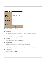 152
152 153
153 154
154 155
155 156
156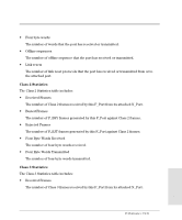 157
157 158
158 159
159