HP Surestore E Tape Library Model 2/20 Tape Library Twenty Slot to Forty Slot - Page 1
HP Surestore E Tape Library Model 2/20 Manual
 |
View all HP Surestore E Tape Library Model 2/20 manuals
Add to My Manuals
Save this manual to your list of manuals |
Page 1 highlights
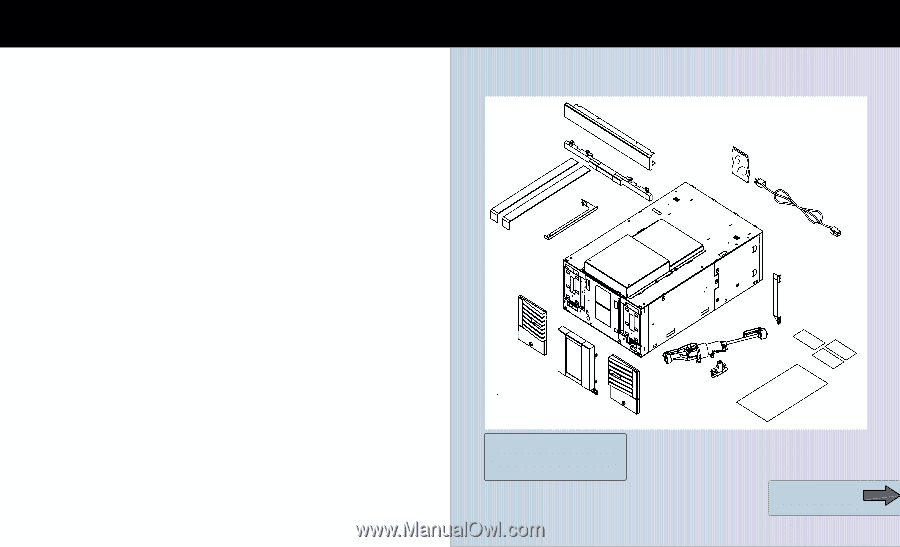
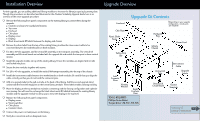
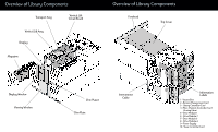
Installation Overview For this upgrade, you are adding additional library modules to increase the library's capacity by twenty slots. Though the procedures are described and illustrated in the Modular Scalability Upgrade Guide, here is an overview of the entire upgrade procedure: 1 Remove the following front panel components on the existing library to protect them during the upgrade: ! Cosmetic enclosure for standalone libraries ! Top cover ! Forehead ! Chin-plate ! Display cover ! Display ! Black sheet-metal RFI shield between the display and chassis 1 Remove the silver label from the top of the existing library to allow the interconnect cable to be connected between the motherboards on both modules. 1 For 20 to 40-slot upgrades, add the vertical lift assembly to the transport assembly. The vertical lift assembly and lift circuit board are included with the upgrade kit and enable the transport to have vertical motion. 1 Install the upgrade module on top of the existing library. Ensure the modules are aligned side-to-side and locked into place. 1 Secure the two modules together with screws. 1 For 20 to 40-slot upgrades, re-install the vertical lift/transport assembly into the top of the chassis. 1 Install the interconnect cable between the motherboards on both modules. Be careful that you align the cable correctly so that you do not bend the connector pins. 1 Add one upgrade label to the pull-out tabs at the back of the library. Add the second upgrade label underneath the front left magazine on the lowest library module. These labels enabls warranty tracking. 1 Move the display to the top module to maintain consistency with the factory configuration and optimize user viewing. You will need to exchange the black sheet-metal RFI shields between the existing library module and the upgrade module to allow you to move the display to the top level. 1 Replace the following front panel components: ! Display cover ! Viewing window ! Chin-plates ! Cosmetic doors 1 Connect the power cord and power on the library. 1 Verify the connection and run diagnostic tests. Upgrade Overview Forehead Chin Plate Plastic Slider Tools Safety Stop Bar Upgrade Kit Contents (Depending on your upgrade configuration, not all parts are included) Hardware Bag Library Chassis Power Cord Left Cosmetic Door Viewing Window Right Cosmetic Door TOOLS REQUIRED: Phillips Screw Driver Torque Driver -T8, T10 , T15, T25 Vertical Lift Assy Interconnect Cable Upgrade Labels Vertical Lift Circuit Board Clipnut Template Overview of Library Components
-
 1
1 -
 2
2
 |
 |