HP TouchSmart tm2-1012tx HP TouchSmart tm2 Notebook PC - Maintenance and Servi - Page 83
that secure the heat sink to the system board.
 |
View all HP TouchSmart tm2-1012tx manuals
Add to My Manuals
Save this manual to your list of manuals |
Page 83 highlights
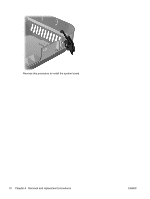
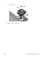
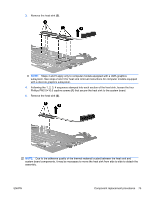
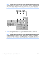
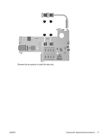
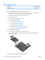
3. Remove the heat sink (2). NOTE: Steps 4 and 5 apply only to computer models equipped with a UMA graphics subsystem. See steps 2 and 3 for heat sink removal instructions for computer models equipped with a discrete graphics subsystem. 4. Following the 1, 2, 3, 4 sequence stamped into each section of the heat sink, loosen the four Phillips PM2.5×10.0 captive screws (1) that secure the heat sink to the system board. 5. Remove the heat sink (2). NOTE: Due to the adhesive quality of the thermal material located between the heat sink and system board components, it may be necessary to move the heat sink from side to side to detach the assembly. ENWW Component replacement procedures 75
-
 1
1 -
2
-
3
-
4
-
5
-
6
-
7
-
8
-
9
-
10
-
11
-
12
-
13
-
14
-
15
-
16
-
17
-
18
-
19
-
20
-
21
-
22
-
23
-
24
-
25
-
26
-
27
-
28
-
29
-
30
-
31
-
32
-
33
-
34
-
35
-
36
-
37
-
38
-
39
-
40
-
41
-
42
-
43
-
44
-
45
-
46
-
47
-
48
-
49
-
50
-
51
-
52
-
53
-
54
-
55
-
56
-
57
-
58
-
59
-
60
-
61
-
62
-
63
-
64
-
65
-
66
-
67
-
68
-
69
-
70
-
71
-
72
-
73
-
74
-
75
-
76
-
77
-
 78
78 -
 79
79 -
 80
80 -
 81
81 -
 82
82 -
 83
83 -
 84
84 -
 85
85 -
 86
86 -
 87
87 -
 88
88 -
89
-
90
-
91
-
92
-
93
-
94
-
95
-
96
-
97
-
98
-
99
-
100
-
101
-
102
-
103
-
104
-
105
-
106
-
107
-
108
-
109
-
110
-
111
-
112
-
113
-
114
-
115
-
116
-
117
-
118
-
119
-
120
-
121
-
122
-
123
-
124
 |
 |
3.
Remove the heat sink
(2)
.
NOTE:
Steps 4 and 5 apply only to computer models equipped with a UMA graphics
subsystem. See steps 2 and 3 for heat sink removal instructions for computer models equipped
with a discrete graphics subsystem.
4.
Following the 1, 2, 3, 4 sequence stamped into each section of the heat sink, loosen the four
Phillips PM2.5×10.0 captive screws
(1)
that secure the heat sink to the system board.
5.
Remove the heat sink
(2)
.
NOTE:
Due to the adhesive quality of the thermal material located between the heat sink and
system board components, it may be necessary to move the heat sink from side to side to detach the
assembly.
ENWW
Component replacement procedures
75