HP TouchSmart tm2-2100 HP TouchSmart tm2 Notebook PC - Maintenance and Service - Page 72
power switch board cable, When replacing the system board
 |
View all HP TouchSmart tm2-2100 manuals
Add to My Manuals
Save this manual to your list of manuals |
Page 72 highlights
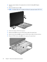
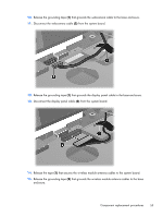
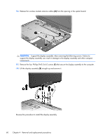
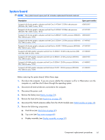
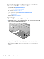
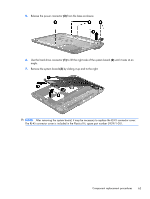
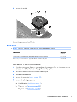
When replacing the system board, be sure that the following components are removed from the defective system board and installed on the replacement system board: ● Memory module (see Memory module on page 40) ● WLAN module (see WLAN module on page 43) ● RTC battery (see RTC battery on page 47) ● Power connector and cable (see Power connector and cable on page 65) ● Fan (see Fan on page 66) ● Heat sink (see Heat sink on page 67) Remove the system board: 1. Disconnect the Bluetooth module cable (1) from the system board. 2. Release the ZIF connector to which the power switch board cable is connected, and disconnect the power switch board cable (2) from the system board. 3. Remove the four Phillips PM2.5×4.0 screws (1) that secure the system board to the base enclosure. 4. Remove the two Phillips PM2.5×4.0 screws (2) that secure the power connector to the base enclosure. 62 Chapter 4 Removal and replacement procedures
-
 1
1 -
2
-
3
-
4
-
5
-
6
-
7
-
8
-
9
-
10
-
11
-
12
-
13
-
14
-
15
-
16
-
17
-
18
-
19
-
20
-
21
-
22
-
23
-
24
-
25
-
26
-
27
-
28
-
29
-
30
-
31
-
32
-
33
-
34
-
35
-
36
-
37
-
38
-
39
-
40
-
41
-
42
-
43
-
44
-
45
-
46
-
47
-
48
-
49
-
50
-
51
-
52
-
53
-
54
-
55
-
56
-
57
-
58
-
59
-
60
-
61
-
62
-
63
-
64
-
65
-
66
-
 67
67 -
 68
68 -
 69
69 -
 70
70 -
 71
71 -
 72
72 -
 73
73 -
 74
74 -
 75
75 -
 76
76 -
 77
77 -
78
-
79
-
80
-
81
-
82
-
83
-
84
-
85
-
86
-
87
-
88
-
89
-
90
-
91
-
92
-
93
-
94
-
95
-
96
-
97
-
98
-
99
-
100
-
101
-
102
-
103
-
104
-
105
-
106
-
107
-
108
-
109
-
110
-
111
-
112
-
113
-
114
-
115
 |
 |