HP VS80 DLT VS80 Tape Drive Installation Poster - Page 1
HP VS80 - StorageWorks DLT VS 80 Tape Drive Manual
 |
UPC - 613326404355
View all HP VS80 manuals
Add to My Manuals
Save this manual to your list of manuals |
Page 1 highlights
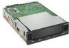
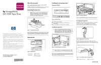
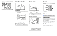
Installation Instructions hp StorageWorks DLT VS80 Tape Drive © Copyright 2003 Hewlett-Packard Development Company, L.P. Hewlett-Packard Company makes no warranty of any kind with regard to this material, including, but not limited to, the implied warranties of merchantability and fitness for a particular purpose. Hewlett-Packard shall not be liable for errors contained herein or for incidental or consequential damages in connection with the furnishing, performance, or use of this material. This document contains proprietary information, which is protected by copyright. No part of this document may be photocopied, reproduced, or translated into another language without the prior written consent of Hewlett-Packard. The information contained in this document is subject to change without notice. Product names mentioned herein may be trademarks of their respective companies as reflected by an associated footnote. Hewlett-Packard Company shall not be liable for technical or editorial errors or omissions contained herein. The information is provided "as is" without warranty of any kind and is subject to change without notice. The warranties for Hewlett-Packard Company products are set forth in the express limited warranty statements for such products. Nothing herein should be construed as constituting an additional warranty. DLT VS80 Tape Drive Installation Instruction Third Edition(September 2003) Part Number: 289066-003 [bar code goes here in text box, if applicable] 289066- 003 About this document This document provides instructions for installing the HP StorageWorks DLT VS80 Tape Drive. Detailed, translated versions of these instructions can be found in the reference guide on the enclosed documentation CD. Unpacking the tape drive Caution: If the room where you are unpacking the drive differs from the temperature at which the tape drive was shipped or stored by 30º F (15º C) or more, let the drive acclimate to the surrounding environment for at least 12 hours before opening the shipping carton. SELECT EJECT Figure 1: Unpacking the tape drive Note: Save the packing materials in case you need to move or ship the drive in the future. You must ship the DLT VS80 tape drive in the original or equivalent packing materials to preserve your warranty. Required tools Installing the internal tape drive Setting the SCSI ID SCSI ID Jumpers SCSI ID 0 1 2 3 4 5 6 7 Jumper Block Figure 3: SCSI ID settings Note: When setting the SCSI ID: ■ Make sure that each SCSI device on a SCSI bus has a unique SCSI ID. ■ Do not use SCSI ID 7. It is reserved for the controller. Installing the tape drive Caution: Electrostatic discharge (ESD) can damage electronic components. Be sure you are properly grounded before beginning this procedure. Refer to Appendix B, "Electrostatic Discharge," in the HP StorageWorks DLT VS80 Tape Drive Reference Guide for additional information. SELECT EJECT ENTER Figure 5: Inserting the tape drive Note: An LVD/SE SCSI host adapter must be present in the server. Terminating the tape drive If the DLT VS80 tape drive is the only SCSI device - other than the SCSI host adapter - on the selected server, it must be terminated. Likewise, if the DLT VS80 tape drive is the last device on the selected server SCSI bus, it must be terminated. Figure 6: Ribbon cable with terminator The DLT VS80 tape drive ships with a ribbon cable that is already terminated as shown in Figure 6. If you use a cable other than the one provided, be sure that the cable is terminated at each end. Figure 2: Required tools External drive: Internal drive: Small screwdriver Phillips screwdriver Torx-15 screwdriver Figure 4: Removing power from all devices Caution: Failure to remove power from all devices could result in damage to the DLT VS80 tape drive or other devices. Note: Your server may differ from the following illustrations. Different rails or cover removal from a drive bay may be required. Refer to the documentation included with your server. 1 2 Figure 7: Connecting the power and signal cable 1 Terminated SCSI cable 2 Power connector See other side
-
 1
1 -
 2
2
 |
 |