| Section |
Page |
| Service Handbook |
1 |
| Service Handbook |
1 |
| Service Handbook |
1 |
| HP Visualize B1000/C3000 UNIX® Workstations |
1 |
| Manufacturing Part Number:� n.a. |
1 |
| Printed in USA ��May 2001 |
1 |
| Edition E0501 |
1 |
| Notice |
2 |
| Notice |
2 |
| The information contained in this document is subject to change without notice. Hewlett-Packard a... |
2 |
| Hewlett-Packard Warranty Statement |
2 |
| Hewlett-Packard Warranty Statement |
2 |
| HP PRODUCT������������������������������� ���DURATION OF WARRANTY ������HP Visualize Wo... |
2 |
| Model B1000/C3000��� |
2 |
| 1. HP warrants HP hardware, accessories and supplies against defects in materials and workmanship... |
2 |
| 1. HP warrants HP hardware, accessories and supplies against defects in materials and workmanship... |
2 |
| 1. HP warrants HP hardware, accessories and supplies against defects in materials and workmanship... |
2 |
| 2. HP warrants that HP software will not fail to execute its programming instructions, for the pe... |
2 |
| 2. HP warrants that HP software will not fail to execute its programming instructions, for the pe... |
2 |
| 3. HP does not warrant that the operation of HP products will be uninterrupted or error free. If ... |
2 |
| 3. HP does not warrant that the operation of HP products will be uninterrupted or error free. If ... |
2 |
| 4. HP products may contain remanufactured parts equivalent to new in performance or may have been... |
2 |
| 4. HP products may contain remanufactured parts equivalent to new in performance or may have been... |
2 |
| 5. The warranty period begins on the date of delivery or on the date of installation if installed... |
2 |
| 5. The warranty period begins on the date of delivery or on the date of installation if installed... |
2 |
| 6. Warranty does not apply to defects resulting from (a) improper or inadequate maintenance or ca... |
2 |
| 6. Warranty does not apply to defects resulting from (a) improper or inadequate maintenance or ca... |
2 |
| 7. TO THE EXTENT ALLOWED BY LOCAL LAW, THE ABOVE WARRANTIES ARE EXCLUSIVE AND NO OTHER WARRANTY O... |
3 |
| 7. TO THE EXTENT ALLOWED BY LOCAL LAW, THE ABOVE WARRANTIES ARE EXCLUSIVE AND NO OTHER WARRANTY O... |
3 |
| 8. HP will be liable for damage to tangible property per incident up to the greater of $300,000 o... |
3 |
| 8. HP will be liable for damage to tangible property per incident up to the greater of $300,000 o... |
3 |
| 9. TO THE EXTENT ALLOWED BY LOCAL LAW, THE REMEDIES IN THIS WARRANTY STATEMENT ARE CUSTOMER’S SOL... |
3 |
| 9. TO THE EXTENT ALLOWED BY LOCAL LAW, THE REMEDIES IN THIS WARRANTY STATEMENT ARE CUSTOMER’S SOL... |
3 |
| Restricted Rights Legend |
3 |
| Restricted Rights Legend |
3 |
| Use, duplication, or disclosure by the U.S. Government Department of Defense is subject to restri... |
3 |
| © Copyright 2001 Hewlett-Packard Company. All Rights Reserved. |
3 |
| This document contains proprietary information that is protected by copyright. All rights are res... |
3 |
| UNIX is a registered trademark in the United States and other countries, licensed exclusively thr... |
3 |
| © Copyright 1980, 1984 AT&T, Inc. |
3 |
| © Copyright 1979, 1980, 1983 The Regents of the University of California. |
3 |
| This software and documentation is based in part on the Fourth Berkeley Software Distribution und... |
3 |
| Printing History |
4 |
| Printing History |
4 |
| New editions of this manual incorporate all material updated since the previous edition. Update p... |
4 |
| The manual part number and printing date indicate its current edition. The manual part number cha... |
4 |
| HP Part Number ��������������Printing Date ������������Edition |
4 |
| Non-Applicable ��������������������May 2001 �������������� First |
4 |
| 1� Product Information |
17 |
| 1� Product Information |
17 |
| This chapter introduces the HP Visualize B1000/C3000 workstations, including their controls and i... |
17 |
| This chapter introduces the HP Visualize B1000/C3000 workstations, including their controls and i... |
17 |
| Included in this chapter are the following topics: |
18 |
| • Product description |
18 |
| • Product description |
18 |
| • Product description |
18 |
| • Product description |
18 |
| • System unit front panel controls |
18 |
| • System unit front panel controls |
18 |
| • System unit rear panel connectors |
18 |
| • System unit rear panel connectors |
18 |
| • Monitor information |
18 |
| • Monitor information |
18 |
| • Keyboard and Mouse information |
18 |
| • Keyboard and Mouse information |
18 |
| • Operating System Overview |
18 |
| • Operating System Overview |
18 |
| B1000/C3000:product description, |
19 |
| B1000/C3000:product description, |
19 |
| B1000/C3000:product description, |
19 |
| The HP Visualize B1000 and C3000 workstations contain the following key features: |
19 |
| The HP Visualize B1000 and C3000 workstations contain the following key features: |
19 |
| • Processor: |
19 |
| • Processor: |
19 |
| • Processor: |
19 |
| — One 300MHz PA8500 processor in the B1000 or one 400MHz PA8500 processor in �����the C3000 |
19 |
| — One 750MHz PA8700 processor in the C3700 |
19 |
| — The PA8500 processor has a 0.5MByte instruction cache and a 1.0MByte data cache |
19 |
| — The PA8700 processor has a 0.75MByte instruction cache and a 1.5MByte data cache |
19 |
| • Operating System: |
19 |
| • Operating System: |
19 |
| The B1000/C3000 requires the HP-UX 10.20 and Workstation Additional Core Enhancements (ACE) for H... |
19 |
| • User Interface: |
19 |
| • User Interface: |
19 |
| HP CDE graphical user interface |
19 |
| • Compatibility: Source and binary code compatible with the Series 700 product family |
19 |
| • Compatibility: Source and binary code compatible with the Series 700 product family |
19 |
| • Monitors: |
19 |
| • Monitors: |
19 |
| — 21-inch 1280¥1024 (stereo capability) and 1600¥1200 color, 75Hz |
19 |
| • Optional Graphics: |
19 |
| • Optional Graphics: |
19 |
| HP Visualize-EG and Visualize fx2 Pro (for B1000) |
19 |
| HP Visualize-EG, Visualize fx2 Pro and Visualize fx4 Pro (for C3000) |
19 |
| • Main Memory: |
19 |
| • Main Memory: |
19 |
| — 128MByte and 256MByte DIMMs for B1000 and C3000 workstations |
19 |
| — Eight memory slots available per each B1000 and C3000 workstations � ����� |
19 |
| — Minimum of 128MBytes and a maximum of 2GBytes of memory (B1000 and C3000) |
19 |
| • Internal Storage Devices: |
19 |
| • Internal Storage Devices: |
19 |
| – Wide Ultra2 Low-Voltage Differential SCSI – up to two: |
19 |
| 9.0 GB Hard Disk Drive |
19 |
| 18.0 GB Hard Disk Drive |
19 |
| – Removable Media (one of each maximum) |
19 |
| CD-ROM Drive |
19 |
| Floppy Disk Drive |
20 |
| • Standard Network: |
20 |
| • Standard Network: |
20 |
| – RJ45, Twisted Pair 10 BaseT/100 BaseT |
20 |
| • Standard I/O Ports: |
20 |
| • Standard I/O Ports: |
20 |
| — Ultra2 Wide Low-Voltage Differential (LVD) SCSI, one |
20 |
| — Ultra Narrow Single-Ended (NSE) SCSI, one |
20 |
| — Parallel port (IEEE 1284), one |
20 |
| — Universal Serial Bus (USB) ports, two |
20 |
| — Serial Interface ports (RS-232C), two |
20 |
| — Audio ports (Line-in, Line-out, headset, and microphone-in) |
20 |
| • Optional I/O: |
20 |
| • Optional I/O: |
20 |
| Six PCI slots are available for the B1000/C3000 workstations. |
20 |
| – 1 PCI 4X:64 bit, 66 MHz, primary graphics (full size, 3.3V) |
20 |
| – 2 PCI 1X:32 bit, 33 MHz, (half size, 5V) |
20 |
| – 3 PCI 2X:64 bit, 33 MHz, (full size, 5V) |
20 |
| • Keyboard: |
20 |
| • Keyboard: |
20 |
| – Universal Serial Bus (USB) keyboard, one |
20 |
| • Mouse: |
20 |
| • Mouse: |
20 |
| – Universal Serial Bus (USB) mouse, one |
20 |
| System Unit Front Panel Controls |
21 |
| System Unit Front Panel Controls |
21 |
| Figure 1-1 shows the location of the system unit front panel controls. |
21 |
| Figure 1-1 shows the location of the system unit front panel controls. |
21 |
| Figure�1�1.� System Unit Front Panel Controls |
21 |
| Figure�1�1.� System Unit Front Panel Controls |
21 |
| <GRAPHIC> |
21 |
| LCD:location, |
21 |
| LCD:location, |
21 |
| The Liquid Crystal Display (LCD) is located on the left side of the front panel. The LCD displays... |
21 |
| LCD:symbols, |
22 |
| LCD:symbols, |
22 |
| LCD:symbols, |
22 |
| <GRAPHIC> |
22 |
| Power switch:soft power down procedure, |
22 |
| Power switch:soft power down procedure, |
22 |
| Use the Power switch to power the system unit on and off. When you use the soft power down proced... |
22 |
| Storage Device:controls and features, |
22 |
| Storage Device:controls and features, |
22 |
| Storage Device:controls and features, |
22 |
| This workstation allows either or both of the following internal storage devices: CD drive or flo... |
22 |
| NOTE You cannot have two internal storage devices of the same type. For example, you cannot have ... |
22 |
| NOTE You cannot have two internal storage devices of the same type. For example, you cannot have ... |
22 |
| Figure 1�3. |
22 |
| Figure 1�3. |
22 |
| Storage device:CD drive, |
23 |
| Storage device:CD drive, |
23 |
| Storage device:CD drive, |
23 |
| <GRAPHIC> |
23 |
| Table�1�1.� CD Drive Controls |
23 |
| <TABLE HEADING> |
23 |
| <TABLE ROW> |
23 |
| Control/Feature |
23 |
| Control/Feature |
23 |
| Purpose |
23 |
| Purpose |
23 |
| <TABLE BODY> |
23 |
| <TABLE ROW> |
23 |
| Eject Button |
23 |
| Press to open the Disc Tray and insert or remove a disc. When the drive is in use, press the ejec... |
23 |
| <TABLE ROW> |
23 |
| Emergency Eject |
23 |
| Emergency Eject |
23 |
| If the workstation does no have power, you can insert the end of a paper clip into this small hol... |
23 |
| If the workstation does no have power, you can insert the end of a paper clip into this small hol... |
23 |
| <TABLE ROW> |
23 |
| Disk Tray |
23 |
| Disk Tray |
23 |
| The Disk Tray holds the CD. This style of CD drive does not use a disk caddy. |
23 |
| The Disk Tray holds the CD. This style of CD drive does not use a disk caddy. |
23 |
| <TABLE ROW> |
23 |
| Busy Indicator |
23 |
| Busy Indicator |
23 |
| Lights during a data access operation and blinks during a data transfer. The indicator blinks ini... |
23 |
| Lights during a data access operation and blinks during a data transfer. The indicator blinks ini... |
23 |
| • A defective disc |
23 |
| • A defective disc |
23 |
| • A defective disc |
23 |
| • A disc insertion error (for example, an upside down disc) |
23 |
| • A disc insertion error (for example, an upside down disc) |
23 |
| • No disc present |
23 |
| • No disc present |
23 |
| NOTE The audio features of the CD drive are supported through applications only. One such applica... |
23 |
| NOTE The audio features of the CD drive are supported through applications only. One such applica... |
23 |
| The optional |
24 |
| Figure 1�4. |
24 |
| Figure 1�4. |
24 |
| Figure�1�4.� Floppy Drive Controls and Features |
24 |
| Figure�1�4.� Floppy Drive Controls and Features |
24 |
| <GRAPHIC> |
24 |
| Table�1�2.� Floppy Drive Controls and Features |
24 |
| <TABLE HEADING> |
24 |
| <TABLE ROW> |
24 |
| Control/Feature |
24 |
| Purpose |
24 |
| Purpose |
24 |
| <TABLE BODY> |
24 |
| <TABLE ROW> |
24 |
| Floppy Drive Eject Button |
24 |
| Floppy Drive Eject Button |
24 |
| Push the eject button to remove floppy diskettes from the drive. |
24 |
| Push the eject button to remove floppy diskettes from the drive. |
24 |
| <TABLE ROW> |
24 |
| Floppy Drive Activity LED |
24 |
| Floppy Drive Activity LED |
24 |
| The floppy drive LED flashes to indicate the drive is in use. |
24 |
| The floppy drive LED flashes to indicate the drive is in use. |
24 |
| Security Lock |
24 |
| Security Lock |
24 |
| Access to the mass storage devices is controlled by a security lock on the front panel. Locking t... |
24 |
| To prevent access to internal components requires the use of the security loop on the rear panel ... |
24 |
| Rear Panel Connectors: |
25 |
| Rear Panel Connectors: |
25 |
| Rear Panel Connectors: |
25 |
| This section describes the following connectors on the system unit’s rear panel: |
25 |
| This section describes the following connectors on the system unit’s rear panel: |
25 |
| • Two serial ports (RS-232) |
25 |
| • Two serial ports (RS-232) |
25 |
| • Two serial ports (RS-232) |
25 |
| • Two serial ports (RS-232) |
25 |
| • Two Universal Serial Bus ports (USB) |
25 |
| • LAN connector, 10 BaseT/100 BaseT |
25 |
| • LAN connector, 10 BaseT/100 BaseT |
25 |
| • HP parallel IEEE 1284 (printer) connector |
25 |
| • Audio connectors (PCI based, line in, line out, headset, and microphone in) |
25 |
| • Audio connectors (PCI based, line in, line out, headset, and microphone in) |
25 |
| • Ultra2 Wide LVD (Low Voltage Differential) SCSI |
25 |
| • Ultra2 Wide LVD (Low Voltage Differential) SCSI |
25 |
| • Ultra Narrow Single-Ended (NSE) SCSI |
25 |
| • Ultra Narrow Single-Ended (NSE) SCSI |
25 |
| • TOC (transfer of control) button |
25 |
| • TOC (transfer of control) button |
25 |
| • AC power cord connector |
25 |
| • AC power cord connector |
25 |
| • Security loop |
25 |
| • Security loop |
25 |
| NOTE To maintain FCC/EMI compliance, verify that all cables are fully seated and properly fastened. |
25 |
| NOTE To maintain FCC/EMI compliance, verify that all cables are fully seated and properly fastened. |
25 |
| Figure�1�5.� System Unit Rear Panel Connectors |
25 |
| Figure�1�5.� System Unit Rear Panel Connectors |
25 |
| <GRAPHIC> |
26 |
| Rear Panel Connectors:audio connectors, |
26 |
| Rear Panel Connectors:audio connectors, |
26 |
| The Model B1000 and C3000 workstations have audio-input and -output capabilities through external... |
26 |
| The rear panel contains the Audio IN (Stereo line-in) and Microphone (Mic-in), and Audio OUT (Ste... |
26 |
| The audio connectors are standard stereo audio mini-jacks (see Figure 1-6). |
26 |
| NOTE Hewlett-Packard recommends using gold-plated plugs available through audio retailers for bes... |
26 |
| NOTE Hewlett-Packard recommends using gold-plated plugs available through audio retailers for bes... |
26 |
| Figure�1�6.� Audio Connectors |
26 |
| Figure�1�6.� Audio Connectors |
26 |
| <GRAPHIC> |
26 |
| Table 1�3. |
26 |
| <TABLE> |
27 |
| Table�1�3.� Audio Electrical Specifications |
27 |
| <TABLE BODY> |
27 |
| <TABLE ROW> |
27 |
| Frequency Response |
27 |
| Frequency Response |
27 |
| 25 to 20KHz |
27 |
| 25 to 20KHz |
27 |
| <TABLE ROW> |
27 |
| Input Sensitivity/Impedance |
27 |
| Input Sensitivity/Impedance |
27 |
| <TABLE ROW> |
27 |
| Line in |
27 |
| Line in |
27 |
| 2.0V pk/47kohm |
27 |
| 2.0V pk/47kohm |
27 |
| <TABLE ROW> |
27 |
| Microphone in |
27 |
| Microphone in |
27 |
| 22mVpk/1kohm |
27 |
| 22mVpk/1kohm |
27 |
| <TABLE ROW> |
27 |
| Max Output Level/Impedance |
27 |
| Max Output Level/Impedance |
27 |
| <TABLE ROW> |
27 |
| Line Out |
27 |
| Line Out |
27 |
| 2.8Vpp/47kohm |
27 |
| 2.8Vpp/47kohm |
27 |
| <TABLE ROW> |
27 |
| Headphone |
27 |
| Headphone |
27 |
| 2.75Vpp/50ohm |
27 |
| 2.75Vpp/50ohm |
27 |
| <TABLE ROW> |
27 |
| Speaker (internal) |
27 |
| Speaker (internal) |
27 |
| 5.88Vpp/48ohm |
27 |
| 5.88Vpp/48ohm |
27 |
| <TABLE ROW> |
27 |
| Output Impedance |
27 |
| Output Impedance |
27 |
| <TABLE ROW> |
27 |
| Line Out |
27 |
| Line Out |
27 |
| 619ohm |
27 |
| 619ohm |
27 |
| <TABLE ROW> |
27 |
| Headphone |
27 |
| Headphone |
27 |
| 118ohm |
27 |
| 118ohm |
27 |
| USB:, |
27 |
| USB:, |
27 |
| USB:, |
27 |
| The USB connectors located on the rear panel of the workstation provide an interface for the keyb... |
27 |
| The USB connectors located on the rear panel of the workstation provide an interface for the keyb... |
27 |
| For more information on the Universal Serial Bus, refer to the following URL: |
27 |
|
27 |
| CAUTION Usage of devices other than USB specification may result in unpredictable functionality a... |
27 |
| CAUTION Usage of devices other than USB specification may result in unpredictable functionality a... |
27 |
| NOTE The USB clip on the rear of the chassis provides strain relief for the USB cables. |
27 |
| NOTE The USB clip on the rear of the chassis provides strain relief for the USB cables. |
27 |
| Rear Panel Connectors:parallel, |
27 |
| Rear Panel Connectors:parallel, |
27 |
| Rear Panel Connectors:parallel, |
27 |
| The 25-pin HP Parallel I/O interface uses IEEE 1284 I/O interface protocols to support peripheral... |
27 |
| The 25-pin HP Parallel I/O interface uses IEEE 1284 I/O interface protocols to support peripheral... |
27 |
| Rear Panel Connectors:network, |
27 |
| Rear Panel Connectors:network, |
27 |
| Rear Panel Connectors:network, |
27 |
| The B1000/C3000 workstations have a built-in Twisted Pair (TP) connector for the 802.3 (ETHERNET)... |
27 |
| Rear Panel Connectors:serial, |
28 |
| Rear Panel Connectors:serial, |
28 |
| Rear Panel Connectors:serial, |
28 |
| There are a variety of peripheral devices that can attach to the RS-232 Serial Input/Output (SIO)... |
28 |
| The SIO ports are programmable, allowing functions such as bit rate, character length, parity, an... |
28 |
| Table 1�4. |
28 |
| Table 1�4. |
28 |
| <TABLE> |
28 |
| Table�1�4.� Serial I/O Pins |
28 |
| <TABLE HEADING> |
28 |
| <TABLE ROW> |
28 |
| Pin No. |
28 |
| Pin No. |
28 |
| Signal |
28 |
| Signal |
28 |
| Description |
28 |
| Description |
28 |
| <TABLE BODY> |
28 |
| <TABLE ROW> |
28 |
| 1 |
28 |
| 1 |
28 |
| DCD |
28 |
| DCD |
28 |
| Data Carrier Detect |
28 |
| Data Carrier Detect |
28 |
| <TABLE ROW> |
28 |
| 2 |
28 |
| 2 |
28 |
| RXD |
28 |
| RXD |
28 |
| Receive Data |
28 |
| <TABLE ROW> |
28 |
| 3 |
28 |
| 3 |
28 |
| TXD |
28 |
| TXD |
28 |
| Transmit Data |
28 |
| <TABLE ROW> |
28 |
| 4 |
28 |
| 4 |
28 |
| DTR |
28 |
| DTR |
28 |
| Data Terminal Ready |
28 |
| <TABLE ROW> |
28 |
| 5 |
28 |
| 5 |
28 |
| GND |
28 |
| GND |
28 |
| Ground |
28 |
| Ground |
28 |
| <TABLE ROW> |
28 |
| 6 |
28 |
| 6 |
28 |
| DSR |
28 |
| DSR |
28 |
| Data Set Ready |
28 |
| Data Set Ready |
28 |
| <TABLE ROW> |
28 |
| 7 |
28 |
| 7 |
28 |
| RTS |
28 |
| RTS |
28 |
| Request To Send |
28 |
| Request To Send |
28 |
| <TABLE ROW> |
28 |
| 8 |
28 |
| 8 |
28 |
| CTS |
28 |
| CTS |
28 |
| Clear To Send |
28 |
| Clear To Send |
28 |
| <TABLE ROW> |
28 |
| 9 |
28 |
| 9 |
28 |
| RI |
28 |
| RI |
28 |
| Ring Indicator |
28 |
| Ring Indicator |
28 |
| SCSI:connectors, |
28 |
| SCSI:connectors, |
28 |
| SCSI:connectors, |
28 |
| The B1000/C3000 workstations have built in SCSI connectors for Ultra2 Wide Low-Voltage Differenti... |
28 |
| NOTE There must ALWAYS be a terminator at both ends of a SCSI bus. This means one internal termin... |
28 |
| NOTE There must ALWAYS be a terminator at both ends of a SCSI bus. This means one internal termin... |
28 |
| Rear Panel Connectors:TOC, |
29 |
| Rear Panel Connectors:TOC, |
29 |
| Rear Panel Connectors:TOC, |
29 |
| The TOC (transfer of control) button interrupts the system and transfers control from the default... |
29 |
| Rear Panel Connectors:power cord |
29 |
| Rear Panel Connectors:power cord |
29 |
| Rear Panel Connectors:power cord |
29 |
| Plug the workstation’s power cord into the power cord connector to provide AC power to the system. |
29 |
| Rear Panel Connectors:security loop, |
29 |
| Rear Panel Connectors:security loop, |
29 |
| Rear Panel Connectors:security loop, |
29 |
| The security loop provides a means of locking the left side panel with a padlock or other locking... |
29 |
| 1. Inspect left side panel for proper seating in the mainframe chassis. |
29 |
| 1. Inspect left side panel for proper seating in the mainframe chassis. |
29 |
| 2. Push in the retractable pin on the spring loaded square fastener. |
29 |
| 2. Push in the retractable pin on the spring loaded square fastener. |
29 |
| 3. Insert the locking device through the top and bottom holes of the square fastener. |
29 |
| 3. Insert the locking device through the top and bottom holes of the square fastener. |
29 |
| 4. Inspect after locking device is in place to assure that the retractable pin is captured in the... |
29 |
| 4. Inspect after locking device is in place to assure that the retractable pin is captured in the... |
29 |
| The internal components of the workstation is now secured. See |
29 |
| NOTE A locking device is not supplied with the workstation; the customer must supply a lock to us... |
29 |
| NOTE A locking device is not supplied with the workstation; the customer must supply a lock to us... |
29 |
| Figure�1�7.� Security Loop Operation |
30 |
| Figure�1�7.� Security Loop Operation |
30 |
| <GRAPHIC> |
31 |
| Monitor:, |
31 |
| Monitor:, |
31 |
| The B1000/C3000 workstations support the following monitors: |
31 |
| The B1000/C3000 workstations support the following monitors: |
31 |
| • 19-inch, 1280¥1024 color monitor (A4575A) |
31 |
| • 19-inch, 1280¥1024 color monitor (A4575A) |
31 |
| • 19-inch, 1280¥1024 color monitor (A4575A) |
31 |
| • 19-inch, 1600¥1200 color monitor (A4575A) |
31 |
| • 19-inch, 1600¥1200 color monitor (A4575A) |
31 |
| • 21-inch, 1280¥1024 color monitor (A4576A) |
31 |
| • 21-inch, 1280¥1024 color monitor (A4576A) |
31 |
| • 21-inch, 1600¥1200 color monitor (A4576A) |
31 |
| • 21-inch, 1600¥1200 color monitor (A4576A) |
31 |
| For information on the A4575A monitors, see: |
31 |
| • HP A4575A Color Monitor CE Handbook |
31 |
| • HP A4575A Color Monitor CE Handbook |
31 |
| • HP A4575A Color Monitor CE Handbook |
31 |
| The A4575A is a 19\ |
31 |
| For information on the A4576A monitor, see: |
31 |
| The A4576A is a 21\ |
31 |
| NOTE Note that the word “multi-sync” is used as a common word to refer to “multi-frequency” and/o... |
31 |
| NOTE Note that the word “multi-sync” is used as a common word to refer to “multi-frequency” and/o... |
31 |
| NOTE The connection to earlier HP monitors with 15-pin mini-DSub cables can be made using the A41... |
31 |
| NOTE The connection to earlier HP monitors with 15-pin mini-DSub cables can be made using the A41... |
31 |
| USB:support, |
32 |
| USB:support, |
32 |
| USB:support, |
32 |
| USB Keyboard |
32 |
| USB Keyboard |
32 |
| The HP Visualize B1000/C3000 workstations support USB keyboards. The keyboard shipped with the wo... |
32 |
| The HP Visualize B1000/C3000 workstations support USB keyboards. The keyboard shipped with the wo... |
32 |
| The USB keyboard is designed specifically for use with HP workstations. All keyboard models with ... |
32 |
| Some applications may expect to use keycodes generated by keys existing on other types of keyboar... |
32 |
| NOTE HIL and PS/2 devices are not supported by the B1000/C3000 workstations. |
32 |
| NOTE HIL and PS/2 devices are not supported by the B1000/C3000 workstations. |
32 |
| USB HP Scroll Mouse |
32 |
| USB HP Scroll Mouse |
32 |
| The HP scroll mouse (USB) has a left and right button that function the same as most mice. Howeve... |
32 |
| The HP scroll mouse (USB) has a left and right button that function the same as most mice. Howeve... |
32 |
| For general information on the various cursor shapes associated with different areas of HP CDE wh... |
32 |
| HP Hub for USB Devices |
32 |
| HP Hub for USB Devices |
32 |
| The HP USB hub (part number D6804) provides the ability to connect more than one USB device to th... |
32 |
| The HP USB hub (part number D6804) provides the ability to connect more than one USB device to th... |
32 |
| Operating System:overview, |
33 |
| Operating System:overview, |
33 |
| Operating System:overview, |
33 |
| The B1000/C3000 workstation uses the HP-UX operating system, version 10.20 and the Workstation Ad... |
33 |
| If you’re running HP-UX 11.0, the result from this command will be similar to this: |
33 |
| Instant Ignition systems (systems with preloaded software) have X-Windows, Hewlett-Packard’s grap... |
33 |
| If the Instant Ignition system does not have the kernel preconfigured with all of the device driv... |
33 |
| For problems or questions with Instant Ignition, refer to |
33 |
| Note that both of the documents mentioned in the previous paragraphs can be found at the followin... |
33 |
| http://www.docs.hp.com/ |
33 |
| http://www.docs.hp.com/ |
33 |
| Memory:, |
34 |
| Memory:, |
34 |
| Memory:, |
34 |
| DIMM:memory, |
34 |
| The main memory for an HP Visualize B1000/C3000 workstation can vary from a minimum of 128 MBytes... |
34 |
| The main memory for an HP Visualize B1000/C3000 workstation can vary from a minimum of 128 MBytes... |
34 |
| To install DIMM cards in the B1000/C3000 workstation reference |
34 |
| Memory:failures, |
34 |
| Memory:failures, |
34 |
| Memory:failures, |
34 |
| DIMM:memory failures, |
34 |
| The HP Visualize B1000/C3000 system (with HP-UX 10.20 and later) uses Memory Page Deallocation, a... |
34 |
| You can use the command |
34 |
| The PDT can also be checked using the |
34 |
| 2� Configuration |
35 |
| 2� Configuration |
35 |
| This chapter provides details about setting up and changing the system configuration for the HP V... |
35 |
| This chapter provides details about setting up and changing the system configuration for the HP V... |
35 |
| Chapter Overview |
36 |
| Chapter Overview |
36 |
| This chapter contains the following sections: |
36 |
| This chapter contains the following sections: |
36 |
| • Workstation Configurations |
36 |
| • Workstation Configurations |
36 |
| • Workstation Configurations |
36 |
| • Field Replaceable Unit (FRU) Configurations |
36 |
| • Field Replaceable Unit (FRU) Configurations |
36 |
| — Internal Storage Devices |
36 |
| — Memory |
36 |
| — I/O Cards |
36 |
| — Monitor-Type Selection |
36 |
| Configuration:workstation, |
37 |
| Configuration:workstation, |
37 |
| Configuration:workstation, |
37 |
| Refer to the HP Workstations Website for a complete list of supported accessories, peripherals, a... |
37 |
| http://www.hp.com/workstations/support/ |
37 |
| http://www.hp.com/workstations/support/ |
37 |
| Configuration:FRU, |
38 |
| Configuration:FRU, |
38 |
| Configuration:FRU, |
38 |
| This section provides information for setting up or changing the configuration of the system Fiel... |
38 |
| This section provides information for setting up or changing the configuration of the system Fiel... |
38 |
| Internal Storage Configurations |
38 |
| Internal Storage Configurations |
38 |
| Configuration:hard disk drive, |
38 |
| Configuration:hard disk drive, |
38 |
| Configuration:hard disk drive, |
38 |
| The SCSI IDs for hard disk drives are hard-wired into the SCA Ultra2 Wide LVD SCSI interfaces in ... |
38 |
| The SCSI IDs for hard disk drives are hard-wired into the SCA Ultra2 Wide LVD SCSI interfaces in ... |
38 |
| Similarly, no jumpers are installed at the factory, nor is any jumper installation required at th... |
38 |
| NOTE There must ALWAYS be a terminator at both ends of a SCSI bus. This means one internal termin... |
38 |
| NOTE There must ALWAYS be a terminator at both ends of a SCSI bus. This means one internal termin... |
38 |
| Table 2-1 lists the default device IDs for internal storage devices. These IDs are the default ID... |
38 |
| <TABLE> |
38 |
| Table�2�1.� Default Device IDs TABLE |
38 |
| <TABLE HEADING> |
38 |
| <TABLE ROW> |
38 |
| Ultra2 Wide Low-Voltage Differential SCSI |
38 |
| <TABLE BODY> |
38 |
| <TABLE ROW> |
38 |
| 1st Hard Disk Drive |
38 |
| ID6 |
38 |
| <TABLE ROW> |
38 |
| 2nd Hard Disk Drive |
38 |
| ID5 |
38 |
| <TABLE ROW> |
38 |
| DDS Drive, external optional device |
38 |
| ID3 |
38 |
| <TABLE ROW> |
38 |
| ** Do not assign SCSI ID7 to any internal storage device. |
38 |
| Figures 2-1 and 2-2 show the two types of hard disk drives supported for the B1000/C3000 workstat... |
38 |
| Figure�2�1.� Hard Drive, 9Gbyte/18Gbyte Ultra2 Low Voltage Differential |
39 |
| Figure�2�1.� Hard Drive, 9Gbyte/18Gbyte Ultra2 Low Voltage Differential |
39 |
| <GRAPHIC> |
39 |
| Figure�2�2.� 9Gbyte, 7200 RPM, Hard Disk Drive |
39 |
| Figure�2�2.� 9Gbyte, 7200 RPM, Hard Disk Drive |
39 |
| <GRAPHIC> |
40 |
| Configuration:hard disk drive:SAM, |
40 |
| Configuration:hard disk drive:SAM, |
40 |
| This section describes how to add a hard drive to your system as a file system using SAM. For mor... |
40 |
| 1. Log in as |
40 |
| 1. Log in as |
40 |
| 1. Log in as |
40 |
| 2. Move the mouse pointer to the Application Manager control for tools and click the left mouse b... |
40 |
| 2. Move the mouse pointer to the Application Manager control for tools and click the left mouse b... |
40 |
| <GRAPHIC> |
40 |
| 3. Click twice on the |
40 |
| <GRAPHIC> |
40 |
| 4. Click twice on the |
40 |
| <GRAPHIC> |
40 |
| 5. Double click on the |
40 |
| <GRAPHIC> |
41 |
| 6. Double click on the |
41 |
| <GRAPHIC> |
41 |
| The following screen message is displayed: �����Scanning the system’s hardware... The Disk and Fi... |
41 |
| 7. Click on |
41 |
| 7. Click on |
41 |
| 8. Enter the mount directory name in the Mount Directory field of the Add Disk window and click o... |
41 |
| 8. Enter the mount directory name in the Mount Directory field of the Add Disk window and click o... |
41 |
| Configuration:CD Drive, |
42 |
| Configuration:CD Drive, |
42 |
| Configuration:CD Drive, |
42 |
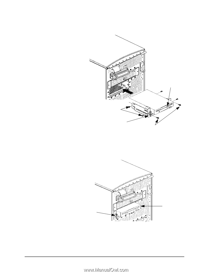
| The optional CD drive connects to the ATAPI (IDE) interface in the CD drive bay backplane within ... |
42 |
| However, as shown in |
42 |
| CAUTION CD-ROM drives are susceptible to mechanical and electrostatic shock. When handling the dr... |
42 |
| CAUTION CD-ROM drives are susceptible to mechanical and electrostatic shock. When handling the dr... |
42 |
| Figure�2�3.� CD Drive Jumper Setting (Rear View) |
42 |
| Figure�2�3.� CD Drive Jumper Setting (Rear View) |
42 |
| <GRAPHIC> |
42 |
| Configuration:floppy disk drive, |
42 |
| Configuration:floppy disk drive, |
42 |
| Configuration:floppy disk drive, |
42 |
| The optional 3.5-inch floppy disk drive requires no ID, switch, or jumper settings. See the secti... |
42 |
| The optional 3.5-inch floppy disk drive requires no ID, switch, or jumper settings. See the secti... |
42 |
| CAUTION Floppy disk drives are susceptible to mechanical and electrostatic shock. When handling t... |
42 |
| CAUTION Floppy disk drives are susceptible to mechanical and electrostatic shock. When handling t... |
42 |
| Configuration:memory, |
43 |
| Configuration:memory, |
43 |
| Configuration:memory, |
43 |
| This workstation has 8 memory slots, labeled 0 through 7. Memory can be configured from 128MB to ... |
43 |
| Figure�2�4.� Memory Connectors |
43 |
| Figure�2�4.� Memory Connectors |
43 |
| <GRAPHIC> |
43 |
| CAUTION The memory cards must be installed in the correct order, else the system will not boot pr... |
43 |
| The B1000/C3000 workstation supports the 128 MByte DIMMs or the 256 MByte DIMMs. If users install... |
44 |
| NOTE Users who wish to achieve both maximum performance and maximum future capacity are advised t... |
44 |
| NOTE Users who wish to achieve both maximum performance and maximum future capacity are advised t... |
44 |
| See the section titled |
44 |
| Use the Boot Console Handler to verify that the workstation recognizes the installed memory. See |
44 |
| Configuration:I/O cards, |
45 |
| Configuration:I/O cards, |
45 |
| Configuration:I/O cards, |
45 |
| There are six I/O slots located on the rear panel of the B1000 and C3000 workstations. Slots 1 th... |
45 |
| There are six I/O slots located on the rear panel of the B1000 and C3000 workstations. Slots 1 th... |
45 |
| Figure�2�5.� PCI Card Slot Numbering and Capabilities |
45 |
| Figure�2�5.� PCI Card Slot Numbering and Capabilities |
45 |
| <GRAPHIC> |
45 |
| NOTE If you connect your monitor to a different graphics card slot, you will need to change the g... |
45 |
| NOTE If you connect your monitor to a different graphics card slot, you will need to change the g... |
45 |
| See the section titled |
45 |
| Monitor: |
46 |
| Monitor: |
46 |
| Monitor: |
46 |
| The B1000/C3000 supports the following monitors: |
46 |
| The B1000/C3000 supports the following monitors: |
46 |
| • 19-inch, 1280¥1024 color monitor, 75 Hz (A4575A) |
46 |
| • 19-inch, 1280¥1024 color monitor, 75 Hz (A4575A) |
46 |
| • 19-inch, 1280¥1024 color monitor, 75 Hz (A4575A) |
46 |
| • 19-inch, 1600¥1200 color monitor, 75 Hz (A4575A) |
46 |
| • 19-inch, 1600¥1200 color monitor, 75 Hz (A4575A) |
46 |
| • 21-inch, 1280¥1024 color monitor (stereo capability), 75 Hz (A4576A) |
46 |
| • 21-inch, 1280¥1024 color monitor (stereo capability), 75 Hz (A4576A) |
46 |
| • 21-inch, 1600¥1200 color monitor, 75 Hz (A4576A) |
46 |
| • 21-inch, 1600¥1200 color monitor, 75 Hz (A4576A) |
46 |
| The |
46 |
| Note that connection to earlier HP monitors with 15-pin mini-DSub cables can be made using the A4... |
46 |
| Monitor:unsupported, |
46 |
| Monitor:unsupported, |
46 |
| Monitor:unsupported, |
46 |
| NOTE The B1000/C3000 workstations support a maximum of four Visualize-EG graphics cards with four... |
46 |
| NOTE The B1000/C3000 workstations support a maximum of four Visualize-EG graphics cards with four... |
46 |
| 3� Troubleshooting |
47 |
| 3� Troubleshooting |
47 |
| This chapter provides information about isolating a failing component, known as a Field Replaceab... |
47 |
| This chapter provides information about isolating a failing component, known as a Field Replaceab... |
47 |
| To troubleshoot a HP Visualize B1000/C3000 workstation, you must be familiar with the HP-UX opera... |
48 |
| As a super-user who is troubleshooting a HP-UX system, you should be able to shutdown and reboot ... |
48 |
| Note any error or status messages, then run the power-up boot ROM diagnostics, known as Self Test... |
48 |
| For a complete description of using |
48 |
| http://wojo.rose.hp.com/ |
48 |
| http://wojo.rose.hp.com/ |
48 |
| troubleshooting: |
49 |
| troubleshooting: |
49 |
| troubleshooting: |
49 |
| The following four figures contain troubleshooting flowcharts you can follow to isolate a failing... |
49 |
| The following four figures contain troubleshooting flowcharts you can follow to isolate a failing... |
49 |
| NOTE For the system to power up, the left side panel must be properly seated in the mainframe cha... |
49 |
| NOTE For the system to power up, the left side panel must be properly seated in the mainframe cha... |
49 |
| Figure�3�1.� Power On LCD, Troubleshooting Flow |
50 |
| Figure�3�1.� Power On LCD, Troubleshooting Flow |
50 |
| <GRAPHIC> |
51 |
| troubleshooting:console, |
51 |
| troubleshooting:console, |
51 |
| <GRAPHIC> |
52 |
| troubleshooting:bootable device, |
52 |
| troubleshooting:bootable device, |
52 |
| <GRAPHIC> |
53 |
| troubleshooting:HP-UX Boot, |
53 |
| troubleshooting:HP-UX Boot, |
53 |
| <GRAPHIC> |
54 |
| troubleshooting:LCD, |
54 |
| troubleshooting:LCD, |
54 |
| This workstation uses an LCD panel to display firmware/OS progress codes. the codes, referred to ... |
54 |
| This workstation uses an LCD panel to display firmware/OS progress codes. the codes, referred to ... |
54 |
| FLT ����A hardware error has been detected |
54 |
| FLT ����A hardware error has been detected |
54 |
| TST ����Hardware being tested |
54 |
| TST ����Hardware being tested |
54 |
| SHU ����System being shutdown |
54 |
| SHU ����System being shutdown |
54 |
| INI ����Hardware being initialized |
54 |
| INI ����Hardware being initialized |
54 |
| WRN ����A non-optimal operating condition exists |
54 |
| WRN ����A non-optimal operating condition exists |
54 |
| RUN ����Computer is running operating system |
54 |
| RUN ����Computer is running operating system |
54 |
| In general, the LCD display has the following format: |
54 |
| <GRAPHIC> |
54 |
| <GRAPHIC> |
54 |
| ZZZ ������������ Three character chassis code |
54 |
| YYYY ������� ��� Four digit hexadecimal code |
54 |
| YYYY ������� ��� Four digit hexadecimal code |
54 |
| FFFFFF ����� ��� Six character field replaceable unit description��� |
54 |
| FFFFFF ����� ��� Six character field replaceable unit description��� |
54 |
| WWWWWWWWWWWWWWWW Description of the chassis code |
54 |
| WWWWWWWWWWWWWWWW Description of the chassis code |
54 |
| If the system encounters an |
54 |
| FLT |
54 |
| FLT |
54 |
| 30FC |
54 |
| 30FC |
54 |
| SYS BD |
54 |
| SYS BD |
54 |
| bad sys bd id |
54 |
| bad sys bd id |
54 |
| troubleshooting:fan failures and warnings, |
55 |
| troubleshooting:fan failures and warnings, |
55 |
| troubleshooting:fan failures and warnings, |
55 |
| This section provides the failure and warning messages you will see in the LCD if there is a prob... |
55 |
| This section provides the failure and warning messages you will see in the LCD if there is a prob... |
55 |
| A chassis code which indicates that a fan has failed ( |
55 |
| <TABLE> |
55 |
| Table�3�1.� Fan Numbers and Corresponding Name |
55 |
| <TABLE HEADING> |
55 |
| <TABLE ROW> |
55 |
| Fan Number |
55 |
| Fan Number |
55 |
| Name of the Fan |
55 |
| Name of the Fan |
55 |
| <TABLE BODY> |
55 |
| <TABLE ROW> |
55 |
| 1 |
55 |
| 1 |
55 |
| (not used) |
55 |
| (not used) |
55 |
| <TABLE ROW> |
55 |
| 2 |
55 |
| 2 |
55 |
| Lower System Fan |
55 |
| Lower System Fan |
55 |
| <TABLE ROW> |
55 |
| 3 |
55 |
| 3 |
55 |
| Upper System Fan |
55 |
| Upper System Fan |
55 |
| <TABLE ROW> |
55 |
| 4 |
55 |
| 4 |
55 |
| PCI Card Fan |
55 |
| PCI Card Fan |
55 |
| <TABLE ROW> |
55 |
| 5 |
55 |
| 5 |
55 |
| Turbo Cooler Fan, CPU |
55 |
| Turbo Cooler Fan, CPU |
55 |
| <TABLE ROW> |
55 |
| 6 |
55 |
| 6 |
55 |
| Disk/Memory Fan |
55 |
| Disk/Memory Fan |
55 |
| Here is an example of a failure message for the I/O (PCI card) fan:���������� |
55 |
| <TABLE> |
55 |
| <TABLE BODY> |
55 |
| <TABLE ROW> |
55 |
| WRN D014 SYS BD |
55 |
| WRN D014 SYS BD |
55 |
| WRN D014 SYS BD |
55 |
| <TABLE ROW> |
55 |
| fan 4: failure! |
55 |
| fan 4: failure! |
55 |
| fan 4: failure! |
55 |
| Here is an example of a warning message for the Turbo Cooler Fan, CPU: |
55 |
| To locate the correct fan, see |
55 |
| Figure�3�5.� Fan Locations |
56 |
| Figure�3�5.� Fan Locations |
56 |
| <GRAPHIC> |
56 |
| • The fan itself, if it is either a system board cooling fan, PCI (I/O) fan, or a memory fan. |
56 |
| • The fan itself, if it is either a system board cooling fan, PCI (I/O) fan, or a memory fan. |
56 |
| • The fan itself, if it is either a system board cooling fan, PCI (I/O) fan, or a memory fan. |
56 |
| • The entire system board tray assembly, if it is a turbo cooler fan (that is, a fan mounted on a... |
56 |
| • The entire system board tray assembly, if it is a turbo cooler fan (that is, a fan mounted on a... |
56 |
| See |
56 |
| troubleshooting:boot failure, |
57 |
| troubleshooting:boot failure, |
57 |
| troubleshooting:boot failure, |
57 |
| To start this workstation from an operating system stored on a device different from the usual bo... |
57 |
| To start this workstation from an operating system stored on a device different from the usual bo... |
57 |
| troubleshooting:bootable media, |
58 |
| troubleshooting:bootable media, |
58 |
| troubleshooting:bootable media, |
58 |
| To list all devices that may contain bootable media, go to the Main Menu of the Boot Console Inte... |
58 |
| To list all devices that may contain bootable media, go to the Main Menu of the Boot Console Inte... |
58 |
| Main Menu: Enter a command or a menu > search ipl |
58 |
| Main Menu: Enter a command or a menu > search ipl |
58 |
| The search may turn up more devices than there are lines on the display. If using a text terminal... |
58 |
| • To hold the display temporarily, press�� |
58 |
| • To hold the display temporarily, press�� |
58 |
| • To hold the display temporarily, press�� |
58 |
| • To continue the display, press �� |
58 |
| • To continue the display, press �� |
58 |
| • To halt the search, press � |
58 |
| • To halt the search, press � |
58 |
| These flow-control commands do not work with a bitmapped display, but such a display can show mor... |
58 |
| To search for devices of just one type that actually contain bootable media, go to the Main Menu ... |
58 |
| Main Menu: Enter a command > search ipl device_type |
58 |
| Main Menu: Enter a command > search ipl device_type |
58 |
| where |
58 |
| • fwscsi |
58 |
| • fwscsi |
58 |
| • fwscsi |
58 |
| • fwscsi |
58 |
| • scsi |
58 |
| • scsi |
58 |
| • scsi |
58 |
| • lan |
58 |
| • lan |
58 |
| • lan |
58 |
| • ide |
58 |
| • ide |
58 |
| • ide |
58 |
| • pcin |
58 |
| • pcin |
58 |
| • pcin |
58 |
| Stable Storage |
58 |
| Stable Storage |
58 |
| Stable Storage is non-volatile memory associated with each PA-RISC processor module. Stable stora... |
58 |
| Stable Storage is non-volatile memory associated with each PA-RISC processor module. Stable stora... |
58 |
| boot command:notations, |
59 |
| boot command:notations, |
59 |
| boot command:notations, |
59 |
| The |
59 |
| The |
59 |
| • Mnemonic |
59 |
| • Mnemonic |
59 |
| • Mnemonic |
59 |
| • Path number |
59 |
| • Path number |
59 |
| Type |
59 |
| Here are examples of mnemonic notation: |
59 |
| • boot |
59 |
| • boot |
59 |
| • boot |
59 |
| • boot |
59 |
| • boot |
59 |
| • boot |
59 |
| • boot |
59 |
| Here is an example of path number notation: |
59 |
| • boot p1 |
59 |
| • boot p1 |
59 |
| • boot p1 |
59 |
| • boot p1 |
59 |
| Supported Boot Paths |
59 |
| Supported Boot Paths |
59 |
| SCSI devices are bootable when connected to the SCSI port on the system. Diskless workstations ca... |
59 |
| SCSI devices are bootable when connected to the SCSI port on the system. Diskless workstations ca... |
59 |
| ISL:environment, |
59 |
| ISL:environment, |
59 |
| ISL:environment, |
59 |
| The ISL environment provides the means to load the operating system (HP-UX) environment. The ISL ... |
59 |
| The ISL environment provides the means to load the operating system (HP-UX) environment. The ISL ... |
59 |
| The ISL program is the first program loaded into main memory from an external media (LAN, disk, o... |
59 |
| The ISL environment provides the following capabilities: |
59 |
| • Execute user-entered commands to modify boot device paths and boot options in stable storage. |
59 |
| • Execute user-entered commands to modify boot device paths and boot options in stable storage. |
59 |
| • Execute user-entered commands to modify boot device paths and boot options in stable storage. |
59 |
| • Run off-line diagnostic programs and utilities. |
59 |
| • Run off-line diagnostic programs and utilities. |
59 |
| • Provide automatic booting of the HP-UX operating system after power-on or reset. |
59 |
| • Provide automatic booting of the HP-UX operating system after power-on or reset. |
59 |
| The ISL program provides a stand-alone environment for loading off-line diagnostic and utility pr... |
59 |
| troubleshooting:selftest failures, |
60 |
| troubleshooting:selftest failures, |
60 |
| troubleshooting:selftest failures, |
60 |
| Chassis codes are the key to debugging selftest errors. If a failure is found during selftest, ch... |
60 |
| Chassis codes are the key to debugging selftest errors. If a failure is found during selftest, ch... |
60 |
| 1. Using |
60 |
| 1. Using |
60 |
| 1. Using |
60 |
| 2. To get additional information about failures from the Boot Console Handler, use the Service Me... |
60 |
| 2. To get additional information about failures from the Boot Console Handler, use the Service Me... |
60 |
| In the following table, the FRU column shows messages printed on the LCD that refer to system FRU... |
60 |
| troubleshooting:chassis codes, |
61 |
| troubleshooting:chassis codes, |
61 |
| troubleshooting:chassis codes, |
61 |
| Table 3�2. |
61 |
| Table 3�2. |
61 |
| Table 3�2. |
61 |
| <TABLE> |
61 |
| Table�3�2.� Chassis Codes for B1000/C3000 Workstations |
61 |
| <TABLE HEADING> |
61 |
| <TABLE ROW> |
61 |
| Ostat |
61 |
| Ostat |
61 |
| Code |
61 |
| Code |
61 |
| FRU |
61 |
| FRU |
61 |
| Message |
61 |
| Message |
61 |
| Description |
61 |
| Description |
61 |
| <TABLE BODY> |
61 |
| <TABLE ROW> |
61 |
| FLT |
61 |
| 1n01 |
61 |
| 1 |
61 |
| SYS BD |
61 |
| SYS BD |
61 |
| HPMC occurred |
61 |
| HPMC occurred |
61 |
| CPU n detected an unexpected HPMC. |
61 |
| CPU |
61 |
| <TABLE ROW> |
61 |
| FLT |
61 |
| 1n02 |
61 |
| SYS BD |
61 |
| SYS BD |
61 |
| powerfail intrpt |
61 |
| powerfail intrpt |
61 |
| CPU n detected an unexpected power fail interrupt. |
61 |
| CPU |
61 |
| <TABLE ROW> |
61 |
| FLT |
61 |
| 1n03 |
61 |
| SYS BD |
61 |
| SYS BD |
61 |
| recvry cntr trap |
61 |
| recvry cntr trap |
61 |
| CPU n detected an unexpected recovery counter trap. |
61 |
| CPU |
61 |
| <TABLE ROW> |
61 |
| FLT |
61 |
| 1n04 |
61 |
| SYS BD |
61 |
| SYS BD |
61 |
| external intrrpt |
61 |
| external intrrpt |
61 |
| CPU n detected an unexpected external interrupt. |
61 |
| CPU |
61 |
| <TABLE ROW> |
61 |
| FLT |
61 |
| 1n05 |
61 |
| SYS BD |
61 |
| SYS BD |
61 |
| LPMC occurred |
61 |
| LPMC occurred |
61 |
| CPU n detected an unexpected LPMC. |
61 |
| CPU |
61 |
| <TABLE ROW> |
61 |
| FLT |
61 |
| 1n06 |
61 |
| SYS BD |
61 |
| SYS BD |
61 |
| ITLB mis/Ipg flt |
61 |
| ITLB mis/Ipg flt |
61 |
| CPU n detected an unexpected ITLB miss or instruction page fault. |
61 |
| CPU |
61 |
| <TABLE ROW> |
61 |
| FLT |
61 |
| 1n07 |
61 |
| SYS BD |
61 |
| SYS BD |
61 |
| I mem prot trap |
61 |
| I mem prot trap |
61 |
| CPU n detected an unexpected instruction memory protection trap. |
61 |
| CPU n detected an unexpected instruction memory protection trap. |
61 |
| <TABLE ROW> |
61 |
| FLT |
61 |
| FLT |
61 |
| 1n08 |
61 |
| 1n08 |
61 |
| SYS BD |
61 |
| SYS BD |
61 |
| illegal inst trp |
61 |
| illegal inst trp |
61 |
| CPU n detected an unexpected illegal instruction trap. |
61 |
| CPU n detected an unexpected illegal instruction trap. |
61 |
| <TABLE ROW> |
61 |
| FLT |
61 |
| FLT |
61 |
| 1n09 |
61 |
| 1n09 |
61 |
| SYS BD |
61 |
| SYS BD |
61 |
| break instr trap |
61 |
| break instr trap |
61 |
| CPU n detected an unexpected break instruction trap. |
61 |
| CPU n detected an unexpected break instruction trap. |
61 |
| <TABLE ROW> |
61 |
| FLT |
61 |
| FLT |
61 |
| 1n0A |
61 |
| 1n0A |
61 |
| SYS BD |
61 |
| SYS BD |
61 |
| privilgd op trap |
61 |
| privilgd op trap |
61 |
| CPU n detected an unexpected privileged operation trap. |
61 |
| CPU n detected an unexpected privileged operation trap. |
61 |
| <TABLE ROW> |
61 |
| FLT |
61 |
| FLT |
61 |
| 1n0B |
61 |
| 1n0B |
61 |
| SYS BD |
61 |
| SYS BD |
61 |
| privlgd reg trap |
61 |
| privlgd reg trap |
61 |
| CPU n detected an unexpected privileged register trap. |
61 |
| CPU n detected an unexpected privileged register trap. |
61 |
| <TABLE ROW> |
61 |
| FLT |
61 |
| FLT |
61 |
| 1n0C |
61 |
| 1n0C |
61 |
| SYS BD |
61 |
| SYS BD |
61 |
| overflow trap |
61 |
| overflow trap |
61 |
| CPU n detected an unexpected overflow trap. |
61 |
| CPU n detected an unexpected overflow trap. |
61 |
| <TABLE ROW> |
61 |
| FLT |
61 |
| FLT |
61 |
| 1n0D |
61 |
| 1n0D |
61 |
| SYS BD |
61 |
| SYS BD |
61 |
| conditional trap |
61 |
| conditional trap |
61 |
| CPU n detected an unexpected conditional trap. |
61 |
| CPU n detected an unexpected conditional trap. |
61 |
| <TABLE ROW> |
61 |
| FLT |
61 |
| FLT |
61 |
| 1n0E |
61 |
| 1n0E |
61 |
| SYS BD |
61 |
| SYS BD |
61 |
| assist exep trap |
61 |
| assist exep trap |
61 |
| CPU n detected an unexpected assist exception trap. |
61 |
| CPU n detected an unexpected assist exception trap. |
61 |
| <TABLE ROW> |
61 |
| FLT |
61 |
| 1n0F |
61 |
| SYS BD |
61 |
| SYS BD |
61 |
| DTLB mis/Dpg flt |
61 |
| DTLB mis/Dpg flt |
61 |
| CPU n detected an unexpected DTLB miss or data page fault. |
61 |
| CPU n detected an unexpected DTLB miss or data page fault. |
61 |
| <TABLE ROW> |
61 |
| FLT |
61 |
| 1n10 |
61 |
| SYS BD |
61 |
| SYS BD |
61 |
| non-acc ITLB mis |
61 |
| non-acc ITLB mis |
61 |
| CPU n detected an unexpected non-access ITLB miss fault. |
61 |
| CPU n detected an unexpected non-access ITLB miss fault. |
61 |
| <TABLE ROW> |
61 |
| FLT |
61 |
| 1n11 |
61 |
| SYS BD |
61 |
| SYS BD |
61 |
| non-acc DTLB mis |
61 |
| non-acc DTLB mis |
61 |
| CPU n detected an unexpected non-access DTLB miss or data page fault. |
61 |
| CPU n detected an unexpected non-access DTLB miss or data page fault. |
61 |
| <TABLE ROW> |
61 |
| FLT |
61 |
| 1n12 |
61 |
| SYS BD |
61 |
| SYS BD |
61 |
| data mem prot tr |
61 |
| data mem prot tr |
61 |
| CPU n detected an unexpected data memory protection trap. |
61 |
| CPU n detected an unexpected data memory protection trap. |
61 |
| <TABLE ROW> |
62 |
| FLT |
62 |
| 1n13 |
62 |
| SYS BD |
62 |
| SYS BD |
62 |
| data mem brk trp |
62 |
| data mem brk trp |
62 |
| CPU n detected an unexpected data memory break trap. |
62 |
| CPU n detected an unexpected data memory break trap. |
62 |
| <TABLE ROW> |
62 |
| FLT |
62 |
| 1n14 |
62 |
| SYS BD |
62 |
| SYS BD |
62 |
| TLB dirty bit tr |
62 |
| TLB dirty bit tr |
62 |
| CPU n detected an unexpected TLB dirty bit trap. |
62 |
| CPU n detected an unexpected TLB dirty bit trap. |
62 |
| <TABLE ROW> |
62 |
| FLT |
62 |
| 1n15 |
62 |
| SYS BD |
62 |
| SYS BD |
62 |
| page refrnce trp |
62 |
| page refrnce trp |
62 |
| CPU n detected an unexpected page reference trap. |
62 |
| CPU n detected an unexpected page reference trap. |
62 |
| <TABLE ROW> |
62 |
| FLT |
62 |
| 1n16 |
62 |
| SYS BD |
62 |
| SYS BD |
62 |
| assist emul trap |
62 |
| assist emul trap |
62 |
| CPU n detected an unexpected assist emulation trap. |
62 |
| CPU n detected an unexpected assist emulation trap. |
62 |
| <TABLE ROW> |
62 |
| FLT |
62 |
| 1n17 |
62 |
| SYS BD |
62 |
| SYS BD |
62 |
| hi-priv xfer trp |
62 |
| hi-priv xfer trp |
62 |
| CPU n detected an unexpected higher-privilege transfer trap. |
62 |
| CPU n detected an unexpected higher-privilege transfer trap. |
62 |
| <TABLE ROW> |
62 |
| FLT |
62 |
| 1n18 |
62 |
| SYS BD |
62 |
| SYS BD |
62 |
| lo-priv xfer trp |
62 |
| lo-priv xfer trp |
62 |
| CPU n detected an unexpected lower-privilege transfer trap. |
62 |
| CPU n detected an unexpected lower-privilege transfer trap. |
62 |
| <TABLE ROW> |
62 |
| FLT |
62 |
| 1n19 |
62 |
| SYS BD |
62 |
| SYS BD |
62 |
| taken branch trp |
62 |
| taken branch trp |
62 |
| CPU n detected an unexpected taken-branch trap. |
62 |
| CPU n detected an unexpected taken-branch trap. |
62 |
| <TABLE ROW> |
62 |
| FLT |
62 |
| 1n1A |
62 |
| SYS BD |
62 |
| SYS BD |
62 |
| data mem acc rts |
62 |
| data mem acc rts |
62 |
| CPU n detected an unexpected data memory access rights trap. |
62 |
| CPU n detected an unexpected data memory access rights trap. |
62 |
| <TABLE ROW> |
62 |
| FLT |
62 |
| 1n1B |
62 |
| SYS BD |
62 |
| SYS BD |
62 |
| data mem prot ID |
62 |
| data mem prot ID |
62 |
| CPU n detected an unexpected data memory protection ID trap. |
62 |
| CPU n detected an unexpected data memory protection ID trap. |
62 |
| <TABLE ROW> |
62 |
| FLT |
62 |
| 1n1C |
62 |
| SYS BD |
62 |
| SYS BD |
62 |
| unalign data ref |
62 |
| unalign data ref |
62 |
| CPU n detected an unexpected unaligned data reference trap. |
62 |
| CPU n detected an unexpected unaligned data reference trap. |
62 |
| <TABLE ROW> |
62 |
| FLT |
62 |
| 1n1D |
62 |
| SYS BD |
62 |
| SYS BD |
62 |
| perf mon intrrpt |
62 |
| perf mon intrrpt |
62 |
| CPU n detected an unexpected performance monitor interrupt. |
62 |
| CPU n detected an unexpected performance monitor interrupt. |
62 |
| <TABLE ROW> |
62 |
| TST |
62 |
| 1n20 |
62 |
| 1n20 |
62 |
| SYS BD |
62 |
| SYS BD |
62 |
| CPUn basic test |
62 |
| CPU |
62 |
| CPU n is starting its basic operations self-test. |
62 |
| CPU n is starting its basic operations self-test. |
62 |
| <TABLE ROW> |
62 |
| TST |
62 |
| TST |
62 |
| 1n21 |
62 |
| 1n21 |
62 |
| SYS BD |
62 |
| SYS BD |
62 |
| CPUn alu test |
62 |
| CPU |
62 |
| CPU n is starting its arithmetic and logical unit self-test. |
62 |
| CPU n is starting its arithmetic and logical unit self-test. |
62 |
| <TABLE ROW> |
62 |
| TST |
62 |
| TST |
62 |
| 1n22 |
62 |
| 1n22 |
62 |
| SYS BD |
62 |
| SYS BD |
62 |
| CPUn branch test |
62 |
| CPU |
62 |
| CPU n is starting its branch instruction self-test. |
62 |
| CPU n is starting its branch instruction self-test. |
62 |
| <TABLE ROW> |
62 |
| TST |
62 |
| 1n23 |
62 |
| 1n23 |
62 |
| SYS BD |
62 |
| SYS BD |
62 |
| CPUn arith cond |
62 |
| CPU |
62 |
| CPU n is starting its arthimetic condition self-test. |
62 |
| CPU n is starting its arthimetic condition self-test. |
62 |
| <TABLE ROW> |
62 |
| TST |
62 |
| TST |
62 |
| 1n24 |
62 |
| 1n24 |
62 |
| SYS BD |
62 |
| SYS BD |
62 |
| CPUn bit opers |
62 |
| CPU |
62 |
| CPU n is starting its bit operation instruction self-test. |
62 |
| CPU n is starting its bit operation instruction self-test. |
62 |
| <TABLE ROW> |
62 |
| TST |
62 |
| 1n25 |
62 |
| 1n25 |
62 |
| SYS BD |
62 |
| SYS BD |
62 |
| CPUn cntrl regs |
62 |
| CPU |
62 |
| CPU n is starting its control register self-test. |
62 |
| CPU n is starting its control register self-test. |
62 |
| <TABLE ROW> |
62 |
| TST |
62 |
| TST |
62 |
| 1n26 |
62 |
| 1n26 |
62 |
| SYS BD |
62 |
| SYS BD |
62 |
| CPUn ext intrpt |
62 |
| CPU |
62 |
| CPU n is starting its external interrupt self-test. |
62 |
| CPU n is starting its external interrupt self-test. |
62 |
| <TABLE ROW> |
63 |
| TST |
63 |
| 1n27 |
63 |
| 1n27 |
63 |
| SYS BD |
63 |
| SYS BD |
63 |
| CPUn itimer test |
63 |
| CPU |
63 |
| CPU n is starting its interval timer self-test. |
63 |
| CPU n is starting its interval timer self-test. |
63 |
| <TABLE ROW> |
63 |
| TST |
63 |
| 1n28 |
63 |
| 1n28 |
63 |
| SYS BD |
63 |
| SYS BD |
63 |
| CPUn multi-media |
63 |
| CPU |
63 |
| CPU n is starting its multi-media instructions self-test. |
63 |
| CPU n is starting its multi-media instructions self-test. |
63 |
| <TABLE ROW> |
63 |
| TST |
63 |
| TST |
63 |
| 1n29 |
63 |
| 1n29 |
63 |
| SYS BD |
63 |
| SYS BD |
63 |
| CPUn shadow reg |
63 |
| CPU |
63 |
| CPU n is starting its shadow register self-test. |
63 |
| CPU n is starting its shadow register self-test. |
63 |
| <TABLE ROW> |
63 |
| TST |
63 |
| TST |
63 |
| 1n2A |
63 |
| 1n2A |
63 |
| SYS BD |
63 |
| SYS BD |
63 |
| CPUn diagnse reg |
63 |
| CPU |
63 |
| CPU n is starting its diagnose register self-test. |
63 |
| CPU n is starting its diagnose register self-test. |
63 |
| <TABLE ROW> |
63 |
| TST |
63 |
| TST |
63 |
| 1n2B |
63 |
| 1n2B |
63 |
| SYS BD |
63 |
| SYS BD |
63 |
| CPUn rdr test |
63 |
| CPU |
63 |
| CPU n is starting its remote diagnose register self-test. |
63 |
| CPU n is starting its remote diagnose register self-test. |
63 |
| <TABLE ROW> |
63 |
| TST |
63 |
| TST |
63 |
| 1n2C |
63 |
| 1n2C |
63 |
| SYS BD |
63 |
| SYS BD |
63 |
| CPUn bypass test |
63 |
| CPU |
63 |
| CPU n is starting its integer bypass operation self-test. |
63 |
| CPU n is starting its integer bypass operation self-test. |
63 |
| <TABLE ROW> |
63 |
| TST |
63 |
| 1n30 |
63 |
| 1n30 |
63 |
| SYS BD |
63 |
| SYS BD |
63 |
| CPUn start est |
63 |
| CPU |
63 |
| CPU n is starting its early (pre-memory) self-tests. |
63 |
| CPU n is starting its early (pre-memory) self-tests. |
63 |
| <TABLE ROW> |
63 |
| WRN |
63 |
| WRN |
63 |
| 1n31 |
63 |
| SYS BD |
63 |
| SYS BD |
63 |
| CPUn skip est |
63 |
| CPU n is bypassing its early self-tests to save time. |
63 |
| CPU n is bypassing its early self-tests to save time. |
63 |
| <TABLE ROW> |
63 |
| FLT |
63 |
| FLT |
63 |
| 1n32 |
63 |
| SYS BD |
63 |
| SYS BD |
63 |
| CPUn bad tst mod |
63 |
| CPU |
63 |
| CPU n detected an unsupported system mode. |
63 |
| CPU n detected an unsupported system mode. |
63 |
| <TABLE ROW> |
63 |
| INI |
63 |
| INI |
63 |
| 1n3C |
63 |
| 1n3C |
63 |
| SYS BD |
63 |
| SYS BD |
63 |
| CPUn initialize |
63 |
| CPU |
63 |
| CPU n is initializing after self-tests. |
63 |
| CPU n is initializing after self-tests. |
63 |
| <TABLE ROW> |
63 |
| TST |
63 |
| TST |
63 |
| 1n3E |
63 |
| SYS BD |
63 |
| SYS BD |
63 |
| CPUn exit est |
63 |
| CPU n finished its early self-tests. |
63 |
| CPU n finished its early self-tests. |
63 |
| <TABLE ROW> |
63 |
| TST |
63 |
| TST |
63 |
| 1nA0 |
63 |
| 1nA0 |
63 |
| SYS BD |
63 |
| SYS BD |
63 |
| CPUn fpu tests |
63 |
| CPU |
63 |
| CPU n is starting its floating-point unit self-tests. |
63 |
| CPU n is starting its floating-point unit self-tests. |
63 |
| <TABLE ROW> |
63 |
| TST |
63 |
| TST |
63 |
| 1nA1 |
63 |
| 1nA1 |
63 |
| SYS BD |
63 |
| SYS BD |
63 |
| CPUn fpu reg tst |
63 |
| CPU |
63 |
| CPU n is starting its floating-point register self-test. |
63 |
| CPU n is starting its floating-point register self-test. |
63 |
| <TABLE ROW> |
63 |
| TST |
63 |
| 1nA2 |
63 |
| 1nA2 |
63 |
| SYS BD |
63 |
| SYS BD |
63 |
| CPUn fpu inst |
63 |
| CPU |
63 |
| CPU n is starting its floating-point instruction self-test. |
63 |
| CPU n is starting its floating-point instruction self-test. |
63 |
| <TABLE ROW> |
63 |
| TST |
63 |
| TST |
63 |
| 1nA3 |
63 |
| 1nA3 |
63 |
| SYS BD |
63 |
| SYS BD |
63 |
| CPUn fpu traps |
63 |
| CPU |
63 |
| CPU n is starting its floating-point trap self-test. |
63 |
| CPU n is starting its floating-point trap self-test. |
63 |
| <TABLE ROW> |
63 |
| TST |
63 |
| TST |
63 |
| 1nA4 |
63 |
| 1nA4 |
63 |
| SYS BD |
63 |
| SYS BD |
63 |
| CPUn fpu misc |
63 |
| CPU |
63 |
| CPU n is starting its floating-point miscellaneous operations self-test. |
63 |
| CPU n is starting its floating-point miscellaneous operations self-test. |
63 |
| <TABLE ROW> |
63 |
| TST |
63 |
| TST |
63 |
| 1nA5 |
63 |
| 1nA5 |
63 |
| SYS BD |
63 |
| SYS BD |
63 |
| CPUn fpu bypass |
63 |
| CPU |
63 |
| CPU n is starting its floating-point bypassing self-test. |
63 |
| CPU n is starting its floating-point bypassing self-test. |
63 |
| <TABLE ROW> |
63 |
| TST |
63 |
| TST |
63 |
| 1nB1 |
63 |
| 1nB1 |
63 |
| SYS BD |
63 |
| SYS BD |
63 |
| CPUn TLB RAM tst |
63 |
| CPU |
63 |
| CPU n is starting its TLB register self-test. |
63 |
| CPU n is starting its TLB register self-test. |
63 |
| <TABLE ROW> |
63 |
| TST |
63 |
| TST |
63 |
| 1nB2 |
63 |
| 1nB2 |
63 |
| SYS BD |
63 |
| SYS BD |
63 |
| CPUn TLB trans |
63 |
| CPU |
63 |
| CPU n is starting its TLB translation self-test. |
63 |
| CPU n is starting its TLB translation self-test. |
63 |
| <TABLE ROW> |
64 |
| FLT |
64 |
| FLT |
64 |
| 1nBA |
64 |
| 1nBA |
64 |
| SYS BD |
64 |
| SYS BD |
64 |
| monarch CPU fail |
64 |
| monarch CPU |
64 |
| The monarch CPU failed. |
64 |
| The monarch CPU failed. |
64 |
| <TABLE ROW> |
64 |
| FLT |
64 |
| FLT |
64 |
| 1nBB |
64 |
| 1nBB |
64 |
| SYS BD |
64 |
| SYS BD |
64 |
| bad CPUn number |
64 |
| bad CPU |
64 |
| The CPU identifier was out of range. |
64 |
| The CPU identifier was out of range. |
64 |
| <TABLE ROW> |
64 |
| FLT |
64 |
| FLT |
64 |
| 1nBF |
64 |
| 1nBF |
64 |
| SYS BD |
64 |
| SYS BD |
64 |
| CPUn halt boot |
64 |
| CPU |
64 |
| Bootstrap failure--machine halted. |
64 |
| Bootstrap failure--machine halted. |
64 |
| <TABLE ROW> |
64 |
| INI |
64 |
| INI |
64 |
| 1nCA |
64 |
| 1nCA |
64 |
| SYS BD |
64 |
| SYS BD |
64 |
| CPUn sys bus arb |
64 |
| CPUn sys bus arb |
64 |
| Monarch CPU is initializing the system bus arbitration. |
64 |
| Monarch CPU is initializing the system bus arbitration. |
64 |
| <TABLE ROW> |
64 |
| WRN |
64 |
| WRN |
64 |
| 1nCD |
64 |
| 1nCD |
64 |
| SYS BD |
64 |
| SYS BD |
64 |
| CPUn deconfig |
64 |
| CPU |
64 |
| CPU n deconfigured itself. |
64 |
| CPU n deconfigured itself. |
64 |
| <TABLE ROW> |
64 |
| WRN |
64 |
| WRN |
64 |
| 1nCE |
64 |
| 1nCE |
64 |
| SYS BD |
64 |
| SYS BD |
64 |
| CPUn extinguish |
64 |
| CPU |
64 |
| PDC_PROC halted CPU n. |
64 |
| PDC_PROC halted CPU n. |
64 |
| <TABLE ROW> |
64 |
| FLT |
64 |
| FLT |
64 |
| 1nCF |
64 |
| 1nCF |
64 |
| SYS BD |
64 |
| SYS BD |
64 |
| slaven failed |
64 |
| slave |
64 |
| Slave CPU n failed self-test. |
64 |
| Slave CPU n failed self-test. |
64 |
| <TABLE ROW> |
64 |
| WRN |
64 |
| WRN |
64 |
| 1mDs |
64 |
| 1mDs |
64 |
| SYS BD |
64 |
| SYS BD |
64 |
| slaves deconfig |
64 |
| slaves deconfig |
64 |
| Monarch CPU m deconfigured slave CPU s. |
64 |
| Monarch CPU m deconfigured slave CPU s. |
64 |
| <TABLE ROW> |
64 |
| WRN |
64 |
| WRN |
64 |
| 1nEF |
64 |
| 1nEF |
64 |
| SYS BD |
64 |
| SYS BD |
64 |
| CPUn slftst warn |
64 |
| CPU |
64 |
| CPU n detected a non-fatal error during its self-tests. |
64 |
| CPU n detected a non-fatal error during its self-tests. |
64 |
| <TABLE ROW> |
64 |
| WRN |
64 |
| WRN |
64 |
| 1mFs |
64 |
| 1mFs |
64 |
| SYS BD |
64 |
| SYS BD |
64 |
| monm stop slaves |
64 |
| mon |
64 |
| Monarch CPU m halted slave CPU s. |
64 |
| Monarch CPU m halted slave CPU s. |
64 |
| <TABLE ROW> |
64 |
| INI |
64 |
| INI |
64 |
| 1nFC |
64 |
| SYS BD |
64 |
| SYS BD |
64 |
| CPUn sync’ing |
64 |
| CPUn sync’ing |
64 |
| CPU n is synchronizing with the rest of the system. |
64 |
| CPU n is synchronizing with the rest of the system. |
64 |
| <TABLE ROW> |
64 |
| INI |
64 |
| INI |
64 |
| 1nFD |
64 |
| SYS BD |
64 |
| SYS BD |
64 |
| CPUn stat wd tst |
64 |
| CPU |
64 |
| CPU n is testing the system status word. |
64 |
| CPU n is testing the system status word. |
64 |
| <TABLE ROW> |
64 |
| FLT |
64 |
| FLT |
64 |
| 1nFF |
64 |
| SYS BD |
64 |
| SYS BD |
64 |
| monarchn selftst |
64 |
| monarch |
64 |
| Monarch CPU n failed self-test. |
64 |
| Monarch CPU n failed self-test. |
64 |
| <TABLE ROW> |
64 |
| TST |
64 |
| TST |
64 |
| 2n20 |
64 |
| SYS BD |
64 |
| SYS BD |
64 |
| CPUn icache RAM |
64 |
| CPU |
64 |
| CPU n is starting its instruction cache RAM self-test. |
64 |
| CPU n is starting its instruction cache RAM self-test. |
64 |
| <TABLE ROW> |
64 |
| FLT |
64 |
| FLT |
64 |
| 2n25 |
64 |
| 2n25 |
64 |
| SYS BD |
64 |
| SYS BD |
64 |
| CPUn ic ld d err |
64 |
| CPU |
64 |
| CPU n detected a data error during data cache load. |
64 |
| CPU n detected a data error during data cache load. |
64 |
| <TABLE ROW> |
64 |
| FLT |
64 |
| FLT |
64 |
| 2n26 |
64 |
| SYS BD |
64 |
| SYS BD |
64 |
| CPUn ic ld t err |
64 |
| CPU |
64 |
| CPU n detected a tag error during data cache load. |
64 |
| CPU n detected a tag error during data cache load. |
64 |
| <TABLE ROW> |
64 |
| TST |
64 |
| TST |
64 |
| 2n30 |
64 |
| SYS BD |
64 |
| SYS BD |
64 |
| CPUn icache tag |
64 |
| CPU |
64 |
| CPU n is starting its instruction cache tag self-test. |
64 |
| CPU n is starting its instruction cache tag self-test. |
64 |
| <TABLE ROW> |
64 |
| TST |
64 |
| TST |
64 |
| 2n40 |
64 |
| SYS BD |
64 |
| SYS BD |
64 |
| CPUn icache par |
64 |
| CPU |
64 |
| CPU n is starting its instruction cache parity detection self-test. |
64 |
| CPU n is starting its instruction cache parity detection self-test. |
64 |
| <TABLE ROW> |
64 |
| TST |
64 |
| TST |
64 |
| 2n50 |
64 |
| 2n50 |
64 |
| SYS BD |
64 |
| SYS BD |
64 |
| CPUn dc stor que |
64 |
| CPU |
64 |
| CPU n is starting its data cache store queue self-test. |
64 |
| CPU n is starting its data cache store queue self-test. |
64 |
| <TABLE ROW> |
64 |
| FLT |
64 |
| FLT |
64 |
| 2n51 |
64 |
| SYS BD |
64 |
| SYS BD |
64 |
| CPUn dc st q err |
64 |
| CPU |
64 |
| CPU n detected an error during its data cache store queue self-test. |
64 |
| CPU n detected an error during its data cache store queue self-test. |
64 |
| <TABLE ROW> |
64 |
| TST |
64 |
| TST |
64 |
| 2n70 |
64 |
| SYS BD |
64 |
| SYS BD |
64 |
| CPUn dcache RAM |
64 |
| CPU |
64 |
| CPU n is starting its data cache RAM self-test. |
64 |
| CPU n is starting its data cache RAM self-test. |
64 |
| <TABLE ROW> |
64 |
| TST |
64 |
| TST |
64 |
| 2n80 |
64 |
| SYS BD |
64 |
| SYS BD |
64 |
| CPUn dcache tag |
64 |
| CPU |
64 |
| CPU n is starting its data cache tag self-test. |
64 |
| CPU n is starting its data cache tag self-test. |
64 |
| <TABLE ROW> |
65 |
| TST |
65 |
| TST |
65 |
| 2n90 |
65 |
| SYS BD |
65 |
| CPUn dcache ECC |
65 |
| CPU |
65 |
| CPU n is starting its data cache ECC self-test. |
65 |
| CPU n is starting its data cache ECC self-test. |
65 |
| <TABLE ROW> |
65 |
| FLT |
65 |
| FLT |
65 |
| 2BAD |
65 |
| SYS BD |
65 |
| SYS BD |
65 |
| assertion fail |
65 |
| assertion fail |
65 |
| A firmware assertion failed. |
65 |
| A firmware assertion failed. |
65 |
| <TABLE ROW> |
65 |
| TST |
65 |
| TST |
65 |
| 3n00 |
65 |
| SYS BD |
65 |
| SYS BD |
65 |
| ROM checksum tst |
65 |
| ROM checksum tst |
65 |
| Monarch CPU n is testing the boot ROM integrity. |
65 |
| Monarch CPU n is testing the boot ROM integrity. |
65 |
| <TABLE ROW> |
65 |
| FLT |
65 |
| FLT |
65 |
| 3n00 |
65 |
| SYS BD |
65 |
| SYS BD |
65 |
| ROM checksum BAD |
65 |
| ROM checksum BAD |
65 |
| The boot ROM failed checksum. |
65 |
| The boot ROM failed checksum. |
65 |
| <TABLE ROW> |
65 |
| INI |
65 |
| INI |
65 |
| 3n00 |
65 |
| SYS BD |
65 |
| SYS BD |
65 |
| ROM checksum ok |
65 |
| ROM checksum ok |
65 |
| The boot ROM passed checksum. |
65 |
| The boot ROM passed checksum. |
65 |
| <TABLE ROW> |
65 |
| TST |
65 |
| TST |
65 |
| 3n01 |
65 |
| SYS BD |
65 |
| SYS BD |
65 |
| PDH control test |
65 |
| PDH control test |
65 |
| Monarch CPU n is testing PDH control register. |
65 |
| Monarch CPU n is testing PDH control register. |
65 |
| <TABLE ROW> |
65 |
| INI |
65 |
| INI |
65 |
| 3n01 |
65 |
| SYS BD |
65 |
| SYS BD |
65 |
| PDH control init |
65 |
| PDH control init |
65 |
| Monarch CPU n is initializing the PDH control register. |
65 |
| Monarch CPU n is initializing the PDH control register. |
65 |
| <TABLE ROW> |
65 |
| FLT |
65 |
| FLT |
65 |
| 3n01 |
65 |
| SYS BD |
65 |
| SYS BD |
65 |
| PDH control err |
65 |
| PDH control err |
65 |
| Monarch CPU n detected an error in the PDH control register. |
65 |
| Monarch CPU n detected an error in the PDH control register. |
65 |
| <TABLE ROW> |
65 |
| TST |
65 |
| TST |
65 |
| 3n02 |
65 |
| SYS BD |
65 |
| SYS BD |
65 |
| scratch RAM test |
65 |
| scratch RAM test |
65 |
| Monarch CPU n is testing scratch RAM. |
65 |
| Monarch CPU n is testing scratch RAM. |
65 |
| <TABLE ROW> |
65 |
| INI |
65 |
| INI |
65 |
| 3n02 |
65 |
| SYS BD |
65 |
| SYS BD |
65 |
| scratch RAM ok |
65 |
| scratch RAM ok |
65 |
| The scratch RAM test failed. |
65 |
| <TABLE ROW> |
65 |
| FLT |
65 |
| FLT |
65 |
| 3n02 |
65 |
| SYS BD |
65 |
| SYS BD |
65 |
| scratch RAM bad |
65 |
| scratch RAM bad |
65 |
| The scratch RAM test passed. |
65 |
| <TABLE ROW> |
65 |
| WRN |
65 |
| WRN |
65 |
| 3n03 |
65 |
| SYS BD |
65 |
| SYS BD |
65 |
| stbl st read err |
65 |
| stbl st read err |
65 |
| CPU n detected a non-fatal error reading the stable store. |
65 |
| <TABLE ROW> |
65 |
| FLT |
65 |
| 3n03 |
65 |
| SYS BD |
65 |
| SYS BD |
65 |
| stbl st read err |
65 |
| stbl st read err |
65 |
| CPU n detected a non-fatal error reading the stable store. |
65 |
| <TABLE ROW> |
65 |
| INI |
65 |
| 3nC4 |
65 |
| SYS BD |
65 |
| SYS BD |
65 |
| clearing EEPROM |
65 |
| clearing EEPROM |
65 |
| Monarch CPU n is clearing the EEPROM. |
65 |
| Monarch CPU n is clearing the EEPROM. |
65 |
| <TABLE ROW> |
65 |
| INI |
65 |
| 3nD4 |
65 |
| SYS BD |
65 |
| SYS BD |
65 |
| deflting EEPROM2 |
65 |
| deflting EEPROM2 |
65 |
| Monarch CPU n is initializing the EEPROM to system defaults. |
65 |
| Monarch CPU n is initializing the EEPROM to system defaults. |
65 |
| <TABLE ROW> |
65 |
| WRN |
65 |
| 3n04 |
65 |
| SYS BD |
65 |
| SYS BD |
65 |
| EEPROM write err |
65 |
| EEPROM write err |
65 |
| CPU n detected a non-fatal error writing the EEPROM. |
65 |
| <TABLE ROW> |
65 |
| FLT |
65 |
| FLT |
65 |
| 3n04 |
65 |
| SYS BD |
65 |
| SYS BD |
65 |
| EEPROM write err |
65 |
| EEPROM write err |
65 |
| CPU n detected a fatal error writing the EEPROM. |
65 |
| CPU n detected a fatal error writing the EEPROM. |
65 |
| <TABLE ROW> |
65 |
| FLT |
65 |
| FLT |
65 |
| 3n05 |
65 |
| SYS BD |
65 |
| SYS BD |
65 |
| EEPROM wrt limit |
65 |
| EEPROM wrt limit |
65 |
| CPU n detected a fatal error writing the EEPROM. |
65 |
| CPU n detected a fatal error writing the EEPROM. |
65 |
| <TABLE ROW> |
65 |
| WRN |
65 |
| WRN |
65 |
| 3n06 |
65 |
| SYS BD |
65 |
| SYS BD |
65 |
| EEPROM read err |
65 |
| EEPROM read err |
65 |
| CPU n detected a non-fatal error reading the EEPROM. |
65 |
| CPU n detected a non-fatal error reading the EEPROM. |
65 |
| <TABLE ROW> |
65 |
| FLT |
65 |
| 3n06 |
65 |
| SYS BD |
65 |
| SYS BD |
65 |
| EEPROM read err |
65 |
| EEPROM read err |
65 |
| CPU n detected a fatal error reading the EEPROM. |
65 |
| CPU n detected a fatal error reading the EEPROM. |
65 |
| <TABLE ROW> |
65 |
| INI |
65 |
| 3n07 |
65 |
| SYS BD |
65 |
| SYS BD |
65 |
| CPUn invoke LDB |
65 |
| CPUn invoke LDB |
65 |
| CPU n is starting the low-level debugger. |
65 |
| CPU n is starting the low-level debugger. |
65 |
| <TABLE ROW> |
66 |
| FLT |
66 |
| 3n09 |
66 |
| SYS BD |
66 |
| SYS BD |
66 |
| bad sys mde byte |
66 |
| bad sys mde byte |
66 |
| CPU n detected an unsupported system mode. |
66 |
| CPU n detected an unsupported system mode. |
66 |
| <TABLE ROW> |
66 |
| WRN |
66 |
| 3n1A |
66 |
| SYS BD |
66 |
| SYS BD |
66 |
| hversion mismtch |
66 |
| hversion mismtch |
66 |
| Stable store hardware version doesn’t match system. |
66 |
| Stable store hardware version doesn’t match system. |
66 |
| <TABLE ROW> |
66 |
| TST |
66 |
| 3n1B |
66 |
| SYS BD |
66 |
| SYS BD |
66 |
| chck model strng |
66 |
| chck model strng |
66 |
| Check model string with version in stable store. |
66 |
| Check model string with version in stable store. |
66 |
| <TABLE ROW> |
66 |
| WRN |
66 |
| 3n1B |
66 |
| SYS BD |
66 |
| SYS BD |
66 |
| model str msmtch |
66 |
| model str msmtch |
66 |
| Model string doesn’t match that in stable store. |
66 |
| Model string doesn’t match that in stable store. |
66 |
| <TABLE ROW> |
66 |
| FLT |
66 |
| 3n1B |
66 |
| SYS BD |
66 |
| SYS BD |
66 |
| fatal model str |
66 |
| fatal model str |
66 |
| Error reading model string from stable store. |
66 |
| Error reading model string from stable store. |
66 |
| <TABLE ROW> |
66 |
| TST |
66 |
| 3n1C |
66 |
| SYS BD |
66 |
| SYS BD |
66 |
| test software ID |
66 |
| test software ID |
66 |
| Check LANIC address. |
66 |
| Check LANIC address. |
66 |
| <TABLE ROW> |
66 |
| WRN |
66 |
| 3n1C |
66 |
| SYS BD |
66 |
| SYS BD |
66 |
| update sw ID |
66 |
| update sw ID |
66 |
| Update LANIC address. |
66 |
| Update LANIC address. |
66 |
| <TABLE ROW> |
66 |
| FLT |
66 |
| 3n1C |
66 |
| SYS BD |
66 |
| SYS BD |
66 |
| update sw ID err |
66 |
| update sw ID err |
66 |
| Error updating LANIC address. |
66 |
| Error updating LANIC address. |
66 |
| <TABLE ROW> |
66 |
| INI |
66 |
| 3n2s |
66 |
| SYS BD |
66 |
| SYS BD |
66 |
| Invoke LDB: s |
66 |
| Invoke LDB: s |
66 |
| CPU n is awaiting the low-level debugger for s more seconds. |
66 |
| CPU |
66 |
| <TABLE ROW> |
66 |
| FLT |
66 |
| FLT |
66 |
| FLT |
66 |
| 3nBC |
66 |
| 3nBC |
66 |
| 3nBC |
66 |
| IO BD |
66 |
| IO BD |
66 |
| IO BD |
66 |
| tick timeout |
66 |
| tick timeout |
66 |
| tick timeout |
66 |
| The real-time clock is ticking too slowly or not at all. |
66 |
| The real-time clock is ticking too slowly or not at all. |
66 |
| <TABLE ROW> |
66 |
| TST |
66 |
| 3nBC |
66 |
| IO BD |
66 |
| test sys clocks |
66 |
| test sys clocks |
66 |
| CPU n is verifying processor clocks with the real-time clock. |
66 |
| CPU n is verifying processor clocks with the real-time clock. |
66 |
| <TABLE ROW> |
66 |
| INI |
66 |
| 3nBC |
66 |
| SYS BD |
66 |
| SYS BD |
66 |
| init sys clocks |
66 |
| init sys clocks |
66 |
| CPU n has initialized the processor clocks. |
66 |
| CPU n has initialized the processor clocks. |
66 |
| <TABLE ROW> |
66 |
| FLT |
66 |
| FLT |
66 |
| 3nCD |
66 |
| IO BD |
66 |
| RTC tick timeout |
66 |
| The real time clock is ticking too slowly or not at all. |
66 |
| <TABLE ROW> |
66 |
| TST |
66 |
| 3nCD |
66 |
| SYS BD |
66 |
| SYS BD |
66 |
| check defaults |
66 |
| check defaults |
66 |
| CPU n is initializing stable store values to system defaults. |
66 |
| CPU |
66 |
| <TABLE ROW> |
66 |
| INI |
66 |
| 3nCD |
66 |
| SYS BD |
66 |
| SYS BD |
66 |
| init defaults |
66 |
| init defaults |
66 |
| CPU n finished initializing stable store values. |
66 |
| CPU |
66 |
| <TABLE ROW> |
66 |
| FLT |
66 |
| 3nCD |
66 |
| SYS BD |
66 |
| SYS BD |
66 |
| init EEPROM err |
66 |
| init EEPROM err |
66 |
| CPU n detected an error writing to stable store. |
66 |
| CPU |
66 |
| <TABLE ROW> |
66 |
| FLT |
66 |
| 3nEC |
66 |
| SYS BD |
66 |
| SYS BD |
66 |
| bad sys config |
66 |
| bad sys config |
66 |
| CPU n detected an illegal CPU board configuration. |
66 |
| CPU |
66 |
| <TABLE ROW> |
66 |
| FLT |
66 |
| 3nF4 |
66 |
| SYS BD |
66 |
| SYS BD |
66 |
| EEPROM boot limt |
66 |
| EEPROM boot limt |
66 |
| CPU n detected a fatal error writing the EEPROM. |
66 |
| CPU |
66 |
| <TABLE ROW> |
66 |
| FLT |
66 |
| 3nFC |
66 |
| SYS BD |
66 |
| SYS BD |
66 |
| bad sys bd id |
66 |
| bad sys bd id |
66 |
| CPU n cannot identify CPU board. |
66 |
| CPU n cannot identify CPU board. |
66 |
| <TABLE ROW> |
66 |
| TST |
66 |
| 4n00 |
66 |
| SYS BD |
66 |
| SYS BD |
66 |
| CPUn start lst |
66 |
| CPU |
66 |
| CPU n is starting its late (with memory) self-tests. |
66 |
| CPU n is starting its late (with memory) self-tests. |
66 |
| <TABLE ROW> |
67 |
| WRN |
67 |
| 4n01 |
67 |
| SYS BD |
67 |
| SYS BD |
67 |
| CPUn skip lst |
67 |
| CPU |
67 |
| CPU n is bypassing its late self-tests to save time. |
67 |
| CPU n is bypassing its late self-tests to save time. |
67 |
| <TABLE ROW> |
67 |
| TST |
67 |
| 4n0E |
67 |
| SYS BD |
67 |
| SYS BD |
67 |
| CPUn exit lst |
67 |
| CPU |
67 |
| CPU n finished its late self-tests. |
67 |
| CPU n finished its late self-tests. |
67 |
| <TABLE ROW> |
67 |
| TST |
67 |
| 4n20 |
67 |
| SYS BD |
67 |
| SYS BD |
67 |
| CPUn lst erly st |
67 |
| CPU |
67 |
| CPU n is re-executing some of its early self-tests from system memory. |
67 |
| CPU n is re-executing some of its early self-tests from system memory. |
67 |
| <TABLE ROW> |
67 |
| TST |
67 |
| 4n21 |
67 |
| SYS BD |
67 |
| SYS BD |
67 |
| CPUn lst basic |
67 |
| CPU |
67 |
| CPU n is re-executing its basic operations self-test. |
67 |
| CPU n is re-executing its basic operations self-test. |
67 |
| <TABLE ROW> |
67 |
| TST |
67 |
| 4n22 |
67 |
| SYS BD |
67 |
| SYS BD |
67 |
| CPUn lst alu |
67 |
| CPU |
67 |
| CPU n is re-executing its arithmetic and logic unit self-test. |
67 |
| CPU n is re-executing its arithmetic and logic unit self-test. |
67 |
| <TABLE ROW> |
67 |
| TST |
67 |
| 4n23 |
67 |
| SYS BD |
67 |
| SYS BD |
67 |
| CPUn lst branch |
67 |
| CPU |
67 |
| CPU n is re-executing its branch instruction self-test. |
67 |
| CPU n is re-executing its branch instruction self-test. |
67 |
| <TABLE ROW> |
67 |
| TST |
67 |
| 4n24 |
67 |
| SYS BD |
67 |
| SYS BD |
67 |
| CPUn lst arth cd |
67 |
| CPU |
67 |
| CPU n is re-executing its arithmetic conditions self-test. |
67 |
| CPU n is re-executing its arithmetic conditions self-test. |
67 |
| <TABLE ROW> |
67 |
| TST |
67 |
| 4n25 |
67 |
| SYS BD |
67 |
| SYS BD |
67 |
| CPUn lst bit ops |
67 |
| CPU |
67 |
| CPU n is re-executing its bit operations self-test. |
67 |
| CPU n is re-executing its bit operations self-test. |
67 |
| <TABLE ROW> |
67 |
| TST |
67 |
| 4n26 |
67 |
| SYS BD |
67 |
| SYS BD |
67 |
| CPUn lst ctl reg |
67 |
| CPU |
67 |
| CPU n is re-executing its control register self-test. |
67 |
| CPU n is re-executing its control register self-test. |
67 |
| <TABLE ROW> |
67 |
| TST |
67 |
| 4n27 |
67 |
| SYS BD |
67 |
| SYS BD |
67 |
| CPUn lst ext int |
67 |
| CPU |
67 |
| CPU n is re-executing its external interrupt self-test. |
67 |
| CPU n is re-executing its external interrupt self-test. |
67 |
| <TABLE ROW> |
67 |
| TST |
67 |
| 4n28 |
67 |
| SYS BD |
67 |
| SYS BD |
67 |
| CPUn lst itimer |
67 |
| CPU |
67 |
| CPU n is re-executing its interval timer self-test. |
67 |
| CPU n is re-executing its interval timer self-test. |
67 |
| <TABLE ROW> |
67 |
| TST |
67 |
| 4n29 |
67 |
| SYS BD |
67 |
| SYS BD |
67 |
| CPUn lst mltimed |
67 |
| CPU |
67 |
| CPU n is re-executing its multi-media instructions self-test. |
67 |
| CPU n is re-executing its multi-media instructions self-test. |
67 |
| <TABLE ROW> |
67 |
| TST |
67 |
| 4n2A |
67 |
| SYS BD |
67 |
| SYS BD |
67 |
| CPUn lst shadow |
67 |
| CPU |
67 |
| CPU n is re-executing its shadow register self-test. |
67 |
| CPU n is re-executing its shadow register self-test. |
67 |
| <TABLE ROW> |
67 |
| TST |
67 |
| 4n2B |
67 |
| SYS BD |
67 |
| SYS BD |
67 |
| CPUn lst dg regs |
67 |
| CPU |
67 |
| CPU n is re-executing its diagnose register self-test. |
67 |
| CPU n is re-executing its diagnose register self-test. |
67 |
| <TABLE ROW> |
67 |
| TST |
67 |
| 4n2C |
67 |
| SYS BD |
67 |
| SYS BD |
67 |
| CPUn lst rdrs |
67 |
| CPU |
67 |
| CPU n is re-executing its remote diagnose register self-test. |
67 |
| CPU n is re-executing its remote diagnose register self-test. |
67 |
| <TABLE ROW> |
67 |
| TST |
67 |
| 4n2D |
67 |
| SYS BD |
67 |
| SYS BD |
67 |
| CPUn lst bypass |
67 |
| CPU |
67 |
| CPU n is re-executing its integer bypass operation self-test. |
67 |
| CPU n is re-executing its integer bypass operation self-test. |
67 |
| <TABLE ROW> |
67 |
| TST |
67 |
| 4n30 |
67 |
| SYS BD |
67 |
| SYS BD |
67 |
| CPUn cache byte |
67 |
| CPU |
67 |
| CPU n is starting its data cache sub-word operations self-test. |
67 |
| CPU n is starting its data cache sub-word operations self-test. |
67 |
| <TABLE ROW> |
67 |
| TST |
67 |
| 4n40 |
67 |
| SYS BD |
67 |
| SYS BD |
67 |
| CPUn cache flush |
67 |
| CPU |
67 |
| CPU n is starting its cache flush self-test. |
67 |
| CPU n is starting its cache flush self-test. |
67 |
| <TABLE ROW> |
67 |
| TST |
67 |
| 4n50 |
67 |
| SYS BD |
67 |
| SYS BD |
67 |
| CPUn icache miss |
67 |
| CPU |
67 |
| CPU n is starting its instruction cache miss self-test. |
67 |
| CPU n is starting its instruction cache miss self-test. |
67 |
| <TABLE ROW> |
68 |
| TST |
68 |
| 4n60 |
68 |
| SYS BD |
68 |
| SYS BD |
68 |
| CPUn dcache miss |
68 |
| CPU |
68 |
| CPU n is starting its data cache miss self-test. |
68 |
| CPU n is starting its data cache miss self-test. |
68 |
| <TABLE ROW> |
68 |
| FLT |
68 |
| 5n00 |
68 |
| SYS BD |
68 |
| SYS BD |
68 |
| unknown bus err |
68 |
| unknown bus err |
68 |
| CPU n detected an unknown error on the system bus (Runway). |
68 |
| CPU n detected an unknown error on the system bus (Runway). |
68 |
| <TABLE ROW> |
68 |
| FLT |
68 |
| 5n02 |
68 |
| SYS BD |
68 |
| SYS BD |
68 |
| path err assertd |
68 |
| path err assertd |
68 |
| CPU n detected a path error on the system bus (Runway). |
68 |
| CPU n detected a path error on the system bus (Runway). |
68 |
| <TABLE ROW> |
68 |
| FLT |
68 |
| 5n04 |
68 |
| SYS BD |
68 |
| SYS BD |
68 |
| data parity err |
68 |
| data parity err |
68 |
| CPU n detected a data, address, or control parity error on the system bus (Runway). |
68 |
| CPU n detected a data, address, or control parity error on the system bus (Runway). |
68 |
| <TABLE ROW> |
68 |
| FLT |
68 |
| 5n07 |
68 |
| SYS BD |
68 |
| SYS BD |
68 |
| Runway dir error |
68 |
| Runway dir error |
68 |
| CPU n detected a directed error on the system bus (Runway). |
68 |
| CPU n detected a directed error on the system bus (Runway). |
68 |
| <TABLE ROW> |
68 |
| FLT |
68 |
| 5n08 |
68 |
| SYS BD |
68 |
| SYS BD |
68 |
| Runway broad err |
68 |
| Runway broad err |
68 |
| CPU n detected a broadcast error on the system bus (Runway). |
68 |
| CPU n detected a broadcast error on the system bus (Runway). |
68 |
| <TABLE ROW> |
68 |
| FLT |
68 |
| 5n0A |
68 |
| SYS BD |
68 |
| SYS BD |
68 |
| illegal response |
68 |
| illegal response |
68 |
| CPU n received data that did not match any outstanding data request. |
68 |
| CPU n received data that did not match any outstanding data request. |
68 |
| <TABLE ROW> |
68 |
| FLT |
68 |
| 5n0B |
68 |
| SYS BD |
68 |
| SYS BD |
68 |
| bus timeout |
68 |
| bus timeout |
68 |
| CPU n timed out before receiving requested data. The responder is logged in the system responder ... |
68 |
| CPU n timed out before receiving requested data. The responder is logged in the system responder ... |
68 |
| <TABLE ROW> |
68 |
| FLT |
68 |
| 5n0C |
68 |
| SYS BD |
68 |
| SYS BD |
68 |
| CPU sync failure |
68 |
| CPU sync failure |
68 |
| CPU n’s synchronizer detected a rule violation on the system bus (Runway). |
68 |
| CPU n’s synchronizer detected a rule violation on the system bus (Runway). |
68 |
| <TABLE ROW> |
68 |
| INI |
68 |
| 7000 |
68 |
| DIMM |
68 |
| DIMM |
68 |
| start DIMM scan |
68 |
| start DIMM scan |
68 |
| Start looking for installed DIMMs. |
68 |
| Start looking for installed DIMMs. |
68 |
| <TABLE ROW> |
68 |
| INI |
68 |
| 7002 |
68 |
| SYS BD |
68 |
| SYS BD |
68 |
| init mem tables |
68 |
| init mem tables |
68 |
| Initialize memory data structures. |
68 |
| Initialize memory data structures. |
68 |
| <TABLE ROW> |
68 |
| FLT |
68 |
| 7004 |
68 |
| SYS BD |
68 |
| SYS BD |
68 |
| mem plt upd fail |
68 |
| mem plt upd fail |
68 |
| Error updating memory platform data. |
68 |
| Error updating memory platform data. |
68 |
| <TABLE ROW> |
68 |
| FLT |
68 |
| 7005 |
68 |
| DIMM |
68 |
| DIMM |
68 |
| insufficient mem |
68 |
| insufficient mem |
68 |
| Insufficient memory detected to continue. |
68 |
| Insufficient memory detected to continue. |
68 |
| <TABLE ROW> |
68 |
| TST |
68 |
| 7010 |
68 |
| DIMM |
68 |
| DIMM |
68 |
| check DIMM order |
68 |
| check DIMM order |
68 |
| Start memory DIMM order check. |
68 |
| Start memory DIMM order check. |
68 |
| <TABLE ROW> |
68 |
| WRN |
68 |
| 7011 |
68 |
| DIMM |
68 |
| DIMM |
68 |
| skip DIMM ord ck |
68 |
| skip DIMM ord ck |
68 |
| Bypass memory DIMM order check. |
68 |
| Bypass memory DIMM order check. |
68 |
| <TABLE ROW> |
68 |
| FLT |
68 |
| 7012 |
68 |
| DIMM |
68 |
| DIMM |
68 |
| DIMM order error |
68 |
| DIMM order error |
68 |
| Memory DIMMs are not in the proper order. |
68 |
| Memory DIMMs are not in the proper order. |
68 |
| <TABLE ROW> |
68 |
| FLT |
68 |
| 7013 |
68 |
| DIMM |
68 |
| DIMM |
68 |
| DIMM order error |
68 |
| DIMM order error |
68 |
| Memory DIMMs are not in the proper order. As a result, the system cannot access one or more DIMMs... |
68 |
| Memory DIMMs are not in the proper order. As a result, the system cannot access one or more DIMMs... |
68 |
| <TABLE ROW> |
68 |
| TST |
68 |
| 7016 |
68 |
| DIMM |
68 |
| DIMM |
68 |
| DIMM pair check |
68 |
| DIMM pair check |
68 |
| Start memory DIMM pair check (DIMMs in a pair (e.g. 0a/0b) must match in J7000). |
68 |
| Start memory DIMM pair check (DIMMs in a pair (e.g. 0a/0b) must match in J7000). |
68 |
| <TABLE ROW> |
68 |
| WRN |
68 |
| 7017 |
68 |
| DIMM |
68 |
| DIMM |
68 |
| skip mem pair ck |
68 |
| skip mem pair ck |
68 |
| Bypass memory DIMM set check. |
68 |
| Bypass memory DIMM set check. |
68 |
| <TABLE ROW> |
68 |
| FLT |
68 |
| 701F |
68 |
| DIMM |
68 |
| DIMM |
68 |
| no memory found |
68 |
| no memory found |
68 |
| Memory scan couldn’t find any DIMMs. |
68 |
| Memory scan couldn’t find any DIMMs. |
68 |
| <TABLE ROW> |
69 |
| TST |
69 |
| 7020 |
69 |
| SYS BD |
69 |
| SYS BD |
69 |
| search for IMM |
69 |
| search for IMM |
69 |
| Try to find a single memory bank to use for the initial memory module. |
69 |
| Try to find a single memory bank to use for the initial memory module. |
69 |
| <TABLE ROW> |
69 |
| TST |
69 |
| 703s |
69 |
| DIMM |
69 |
| DIMM |
69 |
| DIMM s IMM vrfy |
69 |
| DIMM |
69 |
| DIMM s was the initial memory module last boot. Verify it still works. |
69 |
| DIMM s was the initial memory module last boot. Verify it still works. |
69 |
| <TABLE ROW> |
69 |
| FLT |
69 |
| 704s |
69 |
| DIMM |
69 |
| DIMM |
69 |
| DIMM s IMM fail |
69 |
| DIMM |
69 |
| DIMM s failed the initial memory module test. |
69 |
| DIMM s failed the initial memory module test. |
69 |
| <TABLE ROW> |
69 |
| TST |
69 |
| 705s |
69 |
| DIMM |
69 |
| DIMM |
69 |
| DIMM s IMM test |
69 |
| DIMM |
69 |
| Test DIMM in slot s as the initial memory module. |
69 |
| Test DIMM in slot s as the initial memory module. |
69 |
| <TABLE ROW> |
69 |
| INI |
69 |
| 706s |
69 |
| DIMM |
69 |
| DIMM |
69 |
| DIMM s is IMM |
69 |
| DIMM |
69 |
| DIMM s chosen as initial memory module. |
69 |
| DIMM s chosen as initial memory module. |
69 |
| <TABLE ROW> |
69 |
| INI |
69 |
| 70F0 |
69 |
| DIMM |
69 |
| DIMM scan done |
69 |
| DIMM scan done |
69 |
| Memory DIMM scan complete. |
69 |
| Memory DIMM scan complete. |
69 |
| <TABLE ROW> |
69 |
| TST |
69 |
| 7100 |
69 |
| SYS BD |
69 |
| SYS BD |
69 |
| mem register tst |
69 |
| mem register tst |
69 |
| Start testing registers in memory controller. |
69 |
| Start testing registers in memory controller. |
69 |
| <TABLE ROW> |
69 |
| WRN |
69 |
| 7101 |
69 |
| SYS BD |
69 |
| SYS BD |
69 |
| skip mem reg tst |
69 |
| skip mem reg tst |
69 |
| Bypass the memory controller register test. |
69 |
| Bypass the memory controller register test. |
69 |
| <TABLE ROW> |
69 |
| FLT |
69 |
| 7102 |
69 |
| SYS BD |
69 |
| SYS BD |
69 |
| mem addr reg tst |
69 |
| mem addr reg tst |
69 |
| Firmware detected an error in the memory controller address registers. |
69 |
| Firmware detected an error in the memory controller address registers. |
69 |
| <TABLE ROW> |
69 |
| FLT |
69 |
| 7103 |
69 |
| SYS BD |
69 |
| SYS BD |
69 |
| mem mbat reg tst |
69 |
| mem mbat reg tst |
69 |
| Firmware detected an error in the memory controller bank registers. |
69 |
| Firmware detected an error in the memory controller bank registers. |
69 |
| <TABLE ROW> |
69 |
| FLT |
69 |
| 7104 |
69 |
| SYS BD |
69 |
| SYS BD |
69 |
| mem reg tst fail |
69 |
| mem reg tst fail |
69 |
| Firmware detected an error in the memory controller memory registers. |
69 |
| Firmware detected an error in the memory controller memory registers. |
69 |
| <TABLE ROW> |
69 |
| FLT |
69 |
| 7105 |
69 |
| SYS BD |
69 |
| SYS BD |
69 |
| mem err reg test |
69 |
| mem err reg test |
69 |
| Firmware detected an error in the memory controller error registers. |
69 |
| Firmware detected an error in the memory controller error registers. |
69 |
| <TABLE ROW> |
69 |
| FLT |
69 |
| 7106 |
69 |
| SYS BD |
69 |
| SYS BD |
69 |
| mem err clr fail |
69 |
| mem err clr fail |
69 |
| Firmware was unable to clear the error registers after testing. |
69 |
| Firmware was unable to clear the error registers after testing. |
69 |
| <TABLE ROW> |
69 |
| INI |
69 |
| 7200 |
69 |
| DIMM |
69 |
| DIMM |
69 |
| strt DIMM detect |
69 |
| strt DIMM detect |
69 |
| Start the Serial Presence Detection (SPD) to search for memory DIMMs. |
69 |
| Start the Serial Presence Detection (SPD) to search for memory DIMMs. |
69 |
| <TABLE ROW> |
69 |
| INI |
69 |
| 7201 |
69 |
| DIMM |
69 |
| DIMM |
69 |
| DIMM detect x% |
69 |
| DIMM detect |
69 |
| SPD is x% finished. |
69 |
| SPD is x% finished. |
69 |
| <TABLE ROW> |
69 |
| WRN |
69 |
| 7202 |
69 |
| SYS BD |
69 |
| SYS BD |
69 |
| skip DIMM detect |
69 |
| skip DIMM detect |
69 |
| Bypass Serial Presence Detection. |
69 |
| Bypass Serial Presence Detection. |
69 |
| <TABLE ROW> |
69 |
| FLT |
69 |
| 7203 |
69 |
| DIMM |
69 |
| DIMM |
69 |
| unsupp DIMM type |
69 |
| unsupp DIMM type |
69 |
| SPD found an unsupported DIMM type. |
69 |
| SPD found an unsupported DIMM type. |
69 |
| <TABLE ROW> |
69 |
| FLT |
69 |
| 7204 |
69 |
| DIMM |
69 |
| DIMM |
69 |
| SPD fatal error |
69 |
| SPD fatal error |
69 |
| SPD detected an unexpected, fatal error. |
69 |
| SPD detected an unexpected, fatal error. |
69 |
| <TABLE ROW> |
69 |
| INI |
69 |
| 7205 |
69 |
| DIMM |
69 |
| DIMM |
69 |
| add HP DIMM type |
69 |
| add HP DIMM type |
69 |
| New HP manufactured DIMM type added to tables. |
69 |
| New HP manufactured DIMM type added to tables. |
69 |
| <TABLE ROW> |
69 |
| INI |
69 |
| 7206 |
69 |
| DIMM |
69 |
| DIMM |
69 |
| non-HP DIMM type |
69 |
| non-HP DIMM type |
69 |
| New non-HP DIMM type added to tables (use at own risk). |
69 |
| New non-HP DIMM type added to tables (use at own risk). |
69 |
| <TABLE ROW> |
70 |
| FLT |
70 |
| 7207 |
70 |
| DIMM |
70 |
| DIMM |
70 |
| DIMM table full |
70 |
| DIMM table full |
70 |
| The DIMM table is full--cannot add new type. |
70 |
| The DIMM table is full--cannot add new type. |
70 |
| <TABLE ROW> |
70 |
| FLT |
70 |
| 7208 |
70 |
| DIMM |
70 |
| DIMM |
70 |
| no DIMMs found |
70 |
| no DIMMs found |
70 |
| SPD didn’t find any memory DIMMs. |
70 |
| SPD didn’t find any memory DIMMs. |
70 |
| <TABLE ROW> |
70 |
| INI |
70 |
| 721s |
70 |
| DIMM |
70 |
| DIMM |
70 |
| is DIMM s inst? |
70 |
| is DIMM |
70 |
| SPD is checking memory slot s. |
70 |
| SPD is checking memory slot s. |
70 |
| <TABLE ROW> |
70 |
| INI |
70 |
| 722s |
70 |
| DIMM |
70 |
| DIMM |
70 |
| ???? DIMM in s |
70 |
| ???? DIMM in s |
70 |
| SPD found a DIMM in slot s, but can’t determine its size. DIMM will not be used. |
70 |
| SPD found a DIMM in slot s, but can’t determine its size. DIMM will not be used. |
70 |
| <TABLE ROW> |
70 |
| INI |
70 |
| 723s |
70 |
| DIMM |
70 |
| DIMM |
70 |
| 128M DIMM in s |
70 |
| 128M DIMM in s |
70 |
| SPD found a 128MB DIMM in slot s. |
70 |
| SPD found a 128MB DIMM in slot s. |
70 |
| <TABLE ROW> |
70 |
| INI |
70 |
| 724s |
70 |
| DIMM |
70 |
| DIMM |
70 |
| 256M DIMM in s |
70 |
| 256M DIMM in s |
70 |
| SPD found a 256MB DIMM in slot s. |
70 |
| SPD found a 256MB DIMM in slot s. |
70 |
| <TABLE ROW> |
70 |
| INI |
70 |
| 725s |
70 |
| DIMM |
70 |
| DIMM |
70 |
| 512M DIMM in s |
70 |
| 512M DIMM in s |
70 |
| SPD found a 512MB DIMM in slot s. |
70 |
| SPD found a 512MB DIMM in slot s. |
70 |
| <TABLE ROW> |
70 |
| FLT |
70 |
| 72As |
70 |
| DIMM |
70 |
| DIMM |
70 |
| DIMM s checksum |
70 |
| DIMM s checksum |
70 |
| DIMM in slot s failed SPD checksum and will not be used. |
70 |
| DIMM in slot s failed SPD checksum and will not be used. |
70 |
| <TABLE ROW> |
70 |
| FLT |
70 |
| 72Cs |
70 |
| DIMM |
70 |
| DIMM |
70 |
| DIMM s mismatch |
70 |
| DIMM s mismatch |
70 |
| DIMM in slot s didn’t match the other in pair. (J7000 only--DIMMs must be in matched pairs.) |
70 |
| DIMM in slot s didn’t match the other in pair. (J7000 only--DIMMs must be in matched pairs.) |
70 |
| <TABLE ROW> |
70 |
| FLT |
70 |
| 72Ds |
70 |
| DIMM |
70 |
| DIMM |
70 |
| DIMM s load err |
70 |
| Memory DIMMs are not in the proper order. As a result, the system cannot access DIMM s and has de... |
70 |
| Memory DIMMs are not in the proper order. As a result, the system cannot access DIMM s and has de... |
70 |
| <TABLE ROW> |
70 |
| INI |
70 |
| 7300 |
70 |
| SYS BD |
70 |
| SYS BD |
70 |
| mem config start |
70 |
| mem config start |
70 |
| Starting main memory configuration. |
70 |
| Starting main memory configuration. |
70 |
| <TABLE ROW> |
70 |
| TST |
70 |
| TST |
70 |
| 7301 |
70 |
| 7301 |
70 |
| SYS BD |
70 |
| SYS BD |
70 |
| SYS BD |
70 |
| check mem config |
70 |
| check mem config |
70 |
| Checking for memory configuration change since last boot. |
70 |
| Checking for memory configuration change since last boot. |
70 |
| <TABLE ROW> |
70 |
| WRN |
70 |
| 7302 |
70 |
| SYS BD |
70 |
| SYS BD |
70 |
| SYS BD |
70 |
| mem confg changd |
70 |
| mem confg changd |
70 |
| mem confg changd |
70 |
| Memory physical configuration changed since last boot. |
70 |
| Memory physical configuration changed since last boot. |
70 |
| <TABLE ROW> |
70 |
| INI |
70 |
| INI |
70 |
| INI |
70 |
| 7303 |
70 |
| 7303 |
70 |
| 7303 |
70 |
| SYS BD |
70 |
| SYS BD |
70 |
| SYS BD |
70 |
| use saved config |
70 |
| use saved config |
70 |
| use saved config |
70 |
| Memory physical configuration didn’t change. Use stored configuration data. |
70 |
| Memory physical configuration didn’t change. Use stored configuration data. |
70 |
| <TABLE ROW> |
70 |
| INI |
70 |
| INI |
70 |
| INI |
70 |
| 7304 |
70 |
| 7304 |
70 |
| 7304 |
70 |
| SYS BD |
70 |
| SYS BD |
70 |
| SYS BD |
70 |
| build mem intrlv |
70 |
| build mem intrlv |
70 |
| build mem intrlv |
70 |
| Building memory configuration with all DIMMs interleaved. |
70 |
| Building memory configuration with all DIMMs interleaved. |
70 |
| <TABLE ROW> |
70 |
| INI |
70 |
| INI |
70 |
| INI |
70 |
| 7305 |
70 |
| 7305 |
70 |
| 7305 |
70 |
| SYS BD |
70 |
| SYS BD |
70 |
| SYS BD |
70 |
| save mem config |
70 |
| save mem config |
70 |
| save mem config |
70 |
| Saving memory configuration information in non-volatile memory. |
70 |
| Saving memory configuration information in non-volatile memory. |
70 |
| <TABLE ROW> |
70 |
| WRN |
70 |
| 7306 |
70 |
| SYS BD |
70 |
| SYS BD |
70 |
| use alt mem conf |
70 |
| use alt mem conf |
70 |
| Memory will be configured from fixed values, instead of detected DIMMs. |
70 |
| Memory will be configured from fixed values, instead of detected DIMMs. |
70 |
| <TABLE ROW> |
70 |
| INI |
70 |
| 7307 |
70 |
| SYS BD |
70 |
| SYS BD |
70 |
| interleve memory |
70 |
| Generating the memory interleave. |
70 |
| Generating the memory interleave. |
70 |
| <TABLE ROW> |
70 |
| FLT |
70 |
| 7308 |
70 |
| SYS BD |
70 |
| SYS BD |
70 |
| PDT is disabled |
70 |
| PDT is disabled |
70 |
| Firmware detected bad memory pages, but the Page Deallocation Table is disabled. |
70 |
| Firmware detected bad memory pages, but the Page Deallocation Table is disabled. |
70 |
| <TABLE ROW> |
70 |
| FLT |
70 |
| FLT |
70 |
| 7309 |
70 |
| DIMM |
70 |
| insufficient mem |
70 |
| Insufficient error-free memory to continue. |
70 |
| <TABLE ROW> |
71 |
| FLT |
71 |
| 730C |
71 |
| SYS BD |
71 |
| SYS BD |
71 |
| mem intrlv fail |
71 |
| mem intrlv fail |
71 |
| Memory interleave generation failed. |
71 |
| Memory interleave generation failed. |
71 |
| <TABLE ROW> |
71 |
| INI |
71 |
| 730F |
71 |
| SYS BD |
71 |
| SYS BD |
71 |
| mem config done |
71 |
| mem config done |
71 |
| Main memory configuration complete. |
71 |
| Main memory configuration complete. |
71 |
| <TABLE ROW> |
71 |
| TST |
71 |
| 7400 |
71 |
| DIMM |
71 |
| DIMM |
71 |
| non-dest mem tst |
71 |
| non-dest mem tst |
71 |
| Starting non-destructive memory test. |
71 |
| Starting non-destructive memory test. |
71 |
| <TABLE ROW> |
71 |
| TST |
71 |
| 740F |
71 |
| DIMM |
71 |
| DIMM |
71 |
| non-dst tst done |
71 |
| non-dst tst done |
71 |
| Non-destructive memory test complete. |
71 |
| Non-destructive memory test complete. |
71 |
| <TABLE ROW> |
71 |
| INI |
71 |
| 7500 |
71 |
| SYS BD |
71 |
| SYS BD |
71 |
| memory reset |
71 |
| memory reset |
71 |
| Resetting memory system. |
71 |
| Resetting memory system. |
71 |
| <TABLE ROW> |
71 |
| WRN |
71 |
| 7501 |
71 |
| SYS BD |
71 |
| SYS BD |
71 |
| mem log clr warn |
71 |
| mem log clr warn |
71 |
| Memory error logs didn’t clear on first try. |
71 |
| Memory error logs didn’t clear on first try. |
71 |
| <TABLE ROW> |
71 |
| FLT |
71 |
| 7502 |
71 |
| SYS BD |
71 |
| SYS BD |
71 |
| mem err log fail |
71 |
| mem err log fail |
71 |
| Firmware could not clear memory error logs. |
71 |
| Firmware could not clear memory error logs. |
71 |
| <TABLE ROW> |
71 |
| TST |
71 |
| 7600 |
71 |
| DIMM |
71 |
| DIMM |
71 |
| dest mem test |
71 |
| dest mem test |
71 |
| Starting the destructive memory test. |
71 |
| Starting the destructive memory test. |
71 |
| <TABLE ROW> |
71 |
| WRN |
71 |
| 7601 |
71 |
| DIMM |
71 |
| DIMM |
71 |
| mem init only |
71 |
| mem init only |
71 |
| Skip the test, just initialize memory to save time. |
71 |
| Skip the test, just initialize memory to save time. |
71 |
| <TABLE ROW> |
71 |
| TST |
71 |
| 7602 |
71 |
| DIMM |
71 |
| DIMM |
71 |
| tst 1st mem page |
71 |
| tst 1st mem page |
71 |
| Starting 3-pass test of first memory page. |
71 |
| Starting 3-pass test of first memory page. |
71 |
| <TABLE ROW> |
71 |
| TST |
71 |
| 7603 |
71 |
| DIMM |
71 |
| DIMM |
71 |
| tst rest of mem |
71 |
| tst rest of mem |
71 |
| Starting 3-pass test of the rest of memory. |
71 |
| Starting 3-pass test of the rest of memory. |
71 |
| <TABLE ROW> |
71 |
| TST |
71 |
| 7604 |
71 |
| DIMM |
71 |
| DIMM |
71 |
| start 1st pass |
71 |
| start 1st pass |
71 |
| Starting 1st pass of memory test (write pseudorandom sequence). |
71 |
| Starting 1st pass of memory test (write pseudorandom sequence). |
71 |
| <TABLE ROW> |
71 |
| TST |
71 |
| 7605 |
71 |
| DIMM |
71 |
| DIMM |
71 |
| 1st pass x% |
71 |
| 1st pass |
71 |
| First pass is x% complete. |
71 |
| First pass is x% complete. |
71 |
| <TABLE ROW> |
71 |
| TST |
71 |
| 7606 |
71 |
| DIMM |
71 |
| DIMM |
71 |
| start 2nd pass |
71 |
| start 2nd pass |
71 |
| Starting 2nd pass of memory test (verify pseudorandom sequence, write inverse). |
71 |
| Starting 2nd pass of memory test (verify pseudorandom sequence, write inverse). |
71 |
| <TABLE ROW> |
71 |
| TST |
71 |
| 7607 |
71 |
| DIMM |
71 |
| DIMM |
71 |
| 2nd pass x% |
71 |
| 2nd pass |
71 |
| Second pass is x% complete. |
71 |
| Second pass is x% complete. |
71 |
| <TABLE ROW> |
71 |
| TST |
71 |
| 7608 |
71 |
| DIMM |
71 |
| DIMM |
71 |
| start 3rd pass |
71 |
| start 3rd pass |
71 |
| Starting 3rd pass of memory test (verify inverse sequence). |
71 |
| Starting 3rd pass of memory test (verify inverse sequence). |
71 |
| <TABLE ROW> |
71 |
| TST |
71 |
| 7609 |
71 |
| DIMM |
71 |
| DIMM |
71 |
| 3rd pass x% |
71 |
| 3rd pass x% |
71 |
| Third pass is x% complete. |
71 |
| Third pass is x% complete. |
71 |
| <TABLE ROW> |
71 |
| TST |
71 |
| 760A |
71 |
| DIMM |
71 |
| DIMM |
71 |
| start mem init |
71 |
| start mem init |
71 |
| Starting memory initialization. (Initialize to zero to set ECC.) |
71 |
| Starting memory initialization. (Initialize to zero to set ECC.) |
71 |
| <TABLE ROW> |
71 |
| TST |
71 |
| 760B |
71 |
| DIMM |
71 |
| DIMM |
71 |
| mem init x% |
71 |
| mem init |
71 |
| Memory initialization is x% complete. |
71 |
| Memory initialization is x% complete. |
71 |
| <TABLE ROW> |
71 |
| WRN |
71 |
| 760C |
71 |
| DIMM |
71 |
| DIMM |
71 |
| repeat dest test |
71 |
| repeat dest test |
71 |
| Re-execute destructive test for hardware troubleshooting. |
71 |
| Re-execute destructive test for hardware troubleshooting. |
71 |
| <TABLE ROW> |
71 |
| FLT |
71 |
| 760D |
71 |
| DIMM |
71 |
| DIMM |
71 |
| mem code cpy err |
71 |
| mem code cpy err |
71 |
| Firmware tried to copy code from ROM to memory, but the copy didn’t match the original. |
71 |
| <TABLE ROW> |
71 |
| FLT |
71 |
| 7610 |
71 |
| DIMM |
71 |
| DIMM |
71 |
| ECC wrt/read err |
71 |
| Writing and reading back good data caused memory ECC error. |
71 |
| <TABLE ROW> |
71 |
| FLT |
71 |
| 7611 |
71 |
| DIMM |
71 |
| DIMM |
71 |
| ECC single data |
71 |
| ECC single data |
71 |
| Memory ECC test failed to detect single-bit data error. |
71 |
| Memory ECC test failed to detect single-bit data error. |
71 |
| <TABLE ROW> |
72 |
| FLT |
72 |
| 7612 |
72 |
| DIMM |
72 |
| DIMM |
72 |
| ECC single ECC |
72 |
| ECC single ECC |
72 |
| Memory ECC test failed to detect single-bit ECC error. |
72 |
| Memory ECC test failed to detect single-bit ECC error. |
72 |
| <TABLE ROW> |
72 |
| FLT |
72 |
| 7613 |
72 |
| DIMM |
72 |
| DIMM |
72 |
| ECC multipl data |
72 |
| ECC multipl data |
72 |
| Memory ECC test failed to detect multiple-bit data error. |
72 |
| Memory ECC test failed to detect multiple-bit data error. |
72 |
| <TABLE ROW> |
72 |
| FLT |
72 |
| 7614 |
72 |
| DIMM |
72 |
| DIMM |
72 |
| ECC multpl signl |
72 |
| ECC multpl signl |
72 |
| Memory ECC test failed to signal multiple-bit error. |
72 |
| Memory ECC test failed to signal multiple-bit error. |
72 |
| <TABLE ROW> |
72 |
| FLT |
72 |
| 7800 |
72 |
| SYS BD |
72 |
| SYS BD |
72 |
| mem err summary |
72 |
| mem err summary |
72 |
| Printing memory error summary word to RS-232. |
72 |
| <TABLE ROW> |
72 |
| FLT |
72 |
| 7801 |
72 |
| SYS BD |
72 |
| SYS BD |
72 |
| bus ctrl par err |
72 |
| bus ctrl par err |
72 |
| System bus (Runway) control parity error detected. |
72 |
| System bus (Runway) control parity error detected. |
72 |
| <TABLE ROW> |
72 |
| FLT |
72 |
| 7802 |
72 |
| SYS BD |
72 |
| SYS BD |
72 |
| bus addr par err |
72 |
| bus addr par err |
72 |
| System bus (Runway) address parity error detected. |
72 |
| System bus (Runway) address parity error detected. |
72 |
| <TABLE ROW> |
72 |
| FLT |
72 |
| 7803 |
72 |
| SYS BD |
72 |
| SYS BD |
72 |
| bus data par err |
72 |
| bus data par err |
72 |
| System bus (Runway) data parity error detected. |
72 |
| System bus (Runway) data parity error detected. |
72 |
| <TABLE ROW> |
72 |
| FLT |
72 |
| 7804 |
72 |
| SYS BD |
72 |
| SYS BD |
72 |
| mem out of range |
72 |
| mem out of range |
72 |
| Memory access outside configured memory space. |
72 |
| Memory access outside configured memory space. |
72 |
| <TABLE ROW> |
72 |
| FLT |
72 |
| 7805 |
72 |
| SYS BD |
72 |
| SYS BD |
72 |
| bus broadcst err |
72 |
| bus broadcst err |
72 |
| System bus (Runway) broadcast error detected. |
72 |
| System bus (Runway) broadcast error detected. |
72 |
| <TABLE ROW> |
72 |
| FLT |
72 |
| 7806 |
72 |
| SYS BD |
72 |
| SYS BD |
72 |
| mem addr par err |
72 |
| mem addr par err |
72 |
| Memory bus address parity error detected. |
72 |
| Memory bus address parity error detected. |
72 |
| <TABLE ROW> |
72 |
| FLT |
72 |
| 7807 |
72 |
| SYS BD |
72 |
| SYS BD |
72 |
| mem ctlr stat wd |
72 |
| Printing memory controller status word to RS-232. |
72 |
| <TABLE ROW> |
72 |
| FLT |
72 |
| 781s |
72 |
| SYS BD |
72 |
| SYS BD |
72 |
| DIMM s uncor err |
72 |
| DIMM s uncor err |
72 |
| Uncorrectable ECC error detected in DIMM s. |
72 |
| Uncorrectable ECC error detected in DIMM s. |
72 |
| <TABLE ROW> |
72 |
| FLT |
72 |
| 782s |
72 |
| SYS BD |
72 |
| SYS BD |
72 |
| DIMM s corr err |
72 |
| DIMM s corr err |
72 |
| Correctable ECC error detected in DIMM s. |
72 |
| Correctable ECC error detected in DIMM s. |
72 |
| <TABLE ROW> |
72 |
| FLT |
72 |
| 7840 |
72 |
| SYS BD |
72 |
| SYS BD |
72 |
| unexpected HPMC |
72 |
| unexpected HPMC |
72 |
| Unexpected HPMC detected. |
72 |
| Unexpected HPMC detected. |
72 |
| <TABLE ROW> |
72 |
| FLT |
72 |
| FLT |
72 |
| FLT |
72 |
| 7841 |
72 |
| 7841 |
72 |
| 7841 |
72 |
| SYS BD |
72 |
| SYS BD |
72 |
| SYS BD |
72 |
| mem status invld |
72 |
| mem status invld |
72 |
| mem status invld |
72 |
| Memory error status word is invalid. |
72 |
| Memory error status word is invalid. |
72 |
| <TABLE ROW> |
72 |
| FLT |
72 |
| 7842 |
72 |
| SYS BD |
72 |
| SYS BD |
72 |
| mem summ invalid |
72 |
| mem summ invalid |
72 |
| Memory summary word is invalid. |
72 |
| Memory summary word is invalid. |
72 |
| <TABLE ROW> |
72 |
| FLT |
72 |
| 7843 |
72 |
| SYS BD |
72 |
| SYS BD |
72 |
| fwd prog invalid |
72 |
| fwd prog invalid |
72 |
| Memory forward progress word is invalid. |
72 |
| Memory forward progress word is invalid. |
72 |
| <TABLE ROW> |
72 |
| FLT |
72 |
| 7844 |
72 |
| SYS BD |
72 |
| SYS BD |
72 |
| mem HPMC summ wd |
72 |
| mem HPMC summ wd |
72 |
| Printing memory error summary word to RS-232. |
72 |
| <TABLE ROW> |
72 |
| FLT |
72 |
| 7845 |
72 |
| SYS BD |
72 |
| SYS BD |
72 |
| mem ctlr stat wd |
72 |
| Printing memory controller status word to RS-232. |
72 |
| <TABLE ROW> |
72 |
| FLT |
72 |
| 7846 |
72 |
| SYS BD |
72 |
| SYS BD |
72 |
| mem err overflow |
72 |
| mem err overflow |
72 |
| Multiple memory errors detected. |
72 |
| Multiple memory errors detected. |
72 |
| <TABLE ROW> |
73 |
| FLT |
73 |
| 7848 |
73 |
| SYS BD |
73 |
| SYS BD |
73 |
| addr not mapped |
73 |
| addr not mapped |
73 |
| Memory address outside configured memory space. |
73 |
| Memory address outside configured memory space. |
73 |
| <TABLE ROW> |
73 |
| FLT |
73 |
| 785s |
73 |
| DIMM |
73 |
| DIMM |
73 |
| MBE in DIMM s |
73 |
| MBE in DIMM |
73 |
| Destructive memory test detected an uncorrectable memory error in DIMM s. |
73 |
| <TABLE ROW> |
73 |
| FLT |
73 |
| 786s |
73 |
| DIMM |
73 |
| DIMM |
73 |
| SBE&MBE DIMM s |
73 |
| SBE&MBE DIMM |
73 |
| Destructive memory test detected both an uncorrectable and a correctable memory error in DIMM s. |
73 |
| Destructive memory test detected both an uncorrectable and a correctable memory error in DIMM s. |
73 |
| <TABLE ROW> |
73 |
| FLT |
73 |
| 787s |
73 |
| DIMM |
73 |
| DIMM |
73 |
| mem err DIMM s |
73 |
| mem err DIMM |
73 |
| Destructive memory test detected a pattern compare error in DIMM s. |
73 |
| Destructive memory test detected a pattern compare error in DIMM s. |
73 |
| <TABLE ROW> |
73 |
| FLT |
73 |
| 788s |
73 |
| DIMM |
73 |
| DIMM |
73 |
| SBE in DIMM s |
73 |
| SBE in DIMM |
73 |
| Destructive memory test detected a correctable memory error in DIMM s. |
73 |
| <TABLE ROW> |
73 |
| FLT |
73 |
| 7890 |
73 |
| DIMM |
73 |
| DIMM |
73 |
| MBE overwrt SBE |
73 |
| MBE overwrt SBE |
73 |
| Firmware replaced a correctable memory error entry in the PDT with an uncorrectable memory error ... |
73 |
| <TABLE ROW> |
73 |
| FLT |
73 |
| 7891 |
73 |
| DIMM |
73 |
| DIMM |
73 |
| dup entry in PDT |
73 |
| dup entry in PDT |
73 |
| The PDT already contains an entry at that address. |
73 |
| The PDT already contains an entry at that address. |
73 |
| <TABLE ROW> |
73 |
| FLT |
73 |
| 7892 |
73 |
| SYS BD |
73 |
| SYS BD |
73 |
| PDT write error |
73 |
| PDT write error |
73 |
| Error adding the entry to the PDT. |
73 |
| Error adding the entry to the PDT. |
73 |
| <TABLE ROW> |
73 |
| FLT |
73 |
| 7893 |
73 |
| SYS BD |
73 |
| SYS BD |
73 |
| PDT is full |
73 |
| PDT is full |
73 |
| The PDT is full--cannot add new entry. |
73 |
| The PDT is full--cannot add new entry. |
73 |
| <TABLE ROW> |
73 |
| FLT |
73 |
| 7900 |
73 |
| SYS BD |
73 |
| SYS BD |
73 |
| no DMT entry |
73 |
| no DMT entry |
73 |
| Internal error--cannot find DIMM entry. |
73 |
| Internal error--cannot find DIMM entry. |
73 |
| <TABLE ROW> |
73 |
| FLT |
73 |
| 7901 |
73 |
| SYS BD |
73 |
| SYS BD |
73 |
| no rank entry |
73 |
| no rank entry |
73 |
| Internal error--cannot find rank entry. |
73 |
| Internal error--cannot find rank entry. |
73 |
| <TABLE ROW> |
73 |
| FLT |
73 |
| 7902 |
73 |
| SYS BD |
73 |
| SYS BD |
73 |
| bad refrsh intvl |
73 |
| bad refrsh intvl |
73 |
| Computed refresh interval is invalid. |
73 |
| Computed refresh interval is invalid. |
73 |
| <TABLE ROW> |
73 |
| FLT |
73 |
| FLT |
73 |
| 7903 |
73 |
| SYS BD |
73 |
| SYS BD |
73 |
| mem intrlv fail |
73 |
| mem intrlv fail |
73 |
| Cannot generate memory interleave. |
73 |
| Cannot generate memory interleave. |
73 |
| <TABLE ROW> |
73 |
| FLT |
73 |
| 7904 |
73 |
| SYS BD |
73 |
| SYS BD |
73 |
| mem reloc failed |
73 |
| mem reloc failed |
73 |
| Cannot interleave with relocated range (3.75GB - 4.0GB). |
73 |
| Cannot interleave with relocated range (3.75GB - 4.0GB). |
73 |
| <TABLE ROW> |
73 |
| FLT |
73 |
| 7905 |
73 |
| SYS BD |
73 |
| SYS BD |
73 |
| mem intrlv error |
73 |
| mem intrlv error |
73 |
| Undefined memory interleave failure. |
73 |
| Undefined memory interleave failure. |
73 |
| <TABLE ROW> |
73 |
| FLT |
73 |
| 79FF |
73 |
| SYS BD |
73 |
| SYS BD |
73 |
| mem firmware err |
73 |
| mem firmware err |
73 |
| Internal error--never expected this to happen. |
73 |
| Internal error--never expected this to happen. |
73 |
| <TABLE ROW> |
73 |
| WRN |
73 |
| 80F3 |
73 |
| SYS BD |
73 |
| SYS BD |
73 |
| err rd IODC byte |
73 |
| Cannot read IODC from ROM or card. |
73 |
| Cannot read IODC from ROM or card. |
73 |
| <TABLE ROW> |
73 |
| WRN |
73 |
| 80F4 |
73 |
| EXT IO |
73 |
| EXT IO |
73 |
| boot read error |
73 |
| Cannot load IODC entry_init for boot device. |
73 |
| Cannot load IODC entry_init for boot device. |
73 |
| <TABLE ROW> |
73 |
| WRN |
73 |
| 80F5 |
73 |
| EXT IO |
73 |
| EXT IO |
73 |
| boot exec error |
73 |
| boot exec error |
73 |
| Error initializing boot device. |
73 |
| Error initializing boot device. |
73 |
| <TABLE ROW> |
73 |
| WRN |
73 |
| 80F6 |
73 |
| EXT IO |
73 |
| EXT IO |
73 |
| boot read error |
73 |
| boot read error |
73 |
| Cannot load IODC entry_io for boot device. |
73 |
| Cannot load IODC entry_io for boot device. |
73 |
| <TABLE ROW> |
73 |
| WRN |
73 |
| 80F7 |
73 |
| EXT IO |
73 |
| EXT IO |
73 |
| boot IO error |
73 |
| boot IO error |
73 |
| Error detected during boot device I/O. |
73 |
| Error detected during boot device I/O. |
73 |
| <TABLE ROW> |
74 |
| WRN |
74 |
| WRN |
74 |
| 80F8 |
74 |
| EXT IO |
74 |
| EXT IO |
74 |
| invalid boot dev |
74 |
| invalid boot dev |
74 |
| Invalid boot device class; bad IODC? |
74 |
| Invalid boot device class; bad IODC? |
74 |
| <TABLE ROW> |
74 |
| WRN |
74 |
| 80FC |
74 |
| EXT IO |
74 |
| EXT IO |
74 |
| invalid boot dev |
74 |
| invalid boot dev |
74 |
| Unexpected error; bad IODC? |
74 |
| Unexpected error; bad IODC? |
74 |
| <TABLE ROW> |
74 |
| INI |
74 |
| 8800 |
74 |
| IOCARD |
74 |
| IOCARD |
74 |
| PCI BusWlk start |
74 |
| PCI BusWlk start |
74 |
| Starting PCI bus and device discovery. |
74 |
| Starting PCI bus and device discovery. |
74 |
| <TABLE ROW> |
74 |
| INI |
74 |
| INI |
74 |
| INI |
74 |
| 88r1 |
74 |
| 88r1 |
74 |
| 88r1 |
74 |
| IOCARD |
74 |
| IOCARD |
74 |
| IOCARD |
74 |
| PCI Rope r walk |
74 |
| PCI Rope |
74 |
| PCI Rope |
74 |
| r |
74 |
| walk |
74 |
| Starting PCI bus and device discovery on Rope r. |
74 |
| Starting PCI bus and device discovery on Rope r. |
74 |
| <TABLE ROW> |
74 |
| INI |
74 |
| INI |
74 |
| 8802 |
74 |
| 8802 |
74 |
| IOCARD |
74 |
| IOCARD |
74 |
| PCI BusWalk done |
74 |
| PCI BusWalk done |
74 |
| PCI bus and device discovery complete. |
74 |
| PCI bus and device discovery complete. |
74 |
| <TABLE ROW> |
74 |
| INI |
74 |
| INI |
74 |
| 8803 |
74 |
| 8803 |
74 |
| SYS BD |
74 |
| SYS BD |
74 |
| PCI alloc done |
74 |
| PCI alloc done |
74 |
| Done allocating address space for PCI devices. |
74 |
| Done allocating address space for PCI devices. |
74 |
| <TABLE ROW> |
74 |
| INI |
74 |
| INI |
74 |
| INI |
74 |
| 8804 |
74 |
| 8804 |
74 |
| 8804 |
74 |
| SYS BD |
74 |
| SYS BD |
74 |
| SYS BD |
74 |
| PCI config done |
74 |
| PCI config done |
74 |
| PCI config done |
74 |
| Done configuring PCI devices. |
74 |
| Done configuring PCI devices. |
74 |
| <TABLE ROW> |
74 |
| FLT |
74 |
| FLT |
74 |
| FLT |
74 |
| 881r |
74 |
| 881 |
74 |
| 881 |
74 |
| r |
74 |
| IO BD |
74 |
| IO BD |
74 |
| IO BD |
74 |
| R2PCIr not found |
74 |
| R2PCI |
74 |
| Rope-to-PCI bridge r not found. |
74 |
| Rope-to-PCI bridge r not found. |
74 |
| <TABLE ROW> |
74 |
| FLT |
74 |
| FLT |
74 |
| FLT |
74 |
| 883r |
74 |
| 883r |
74 |
| 883r |
74 |
| IO BD |
74 |
| IO BD |
74 |
| IO BD |
74 |
| Rope r config err |
74 |
| Rope |
74 |
| PCI configuration failed below Rope-to-PCI bridge r. |
74 |
| PCI configuration failed below Rope-to-PCI bridge r. |
74 |
| <TABLE ROW> |
74 |
| FLT |
74 |
| FLT |
74 |
| FLT |
74 |
| 884r |
74 |
| 884r |
74 |
| 884r |
74 |
| EXT IO |
74 |
| EXT IO |
74 |
| EXT IO |
74 |
| Rope r tgl fail |
74 |
| Rope r tgl fail |
74 |
| Rope r tgl fail |
74 |
| Rope r debug register toggle failed. |
74 |
| Rope r debug register toggle failed. |
74 |
| <TABLE ROW> |
74 |
| INI |
74 |
| INI |
74 |
| INI |
74 |
| 8850 |
74 |
| 8850 |
74 |
| 8850 |
74 |
| SYS_BD |
74 |
| SYS_BD |
74 |
| SYS_BD |
74 |
| early rope0 init |
74 |
| early rope0 init |
74 |
| early rope0 init |
74 |
| Initializing rope 0 for early RS-232 output. |
74 |
| Initializing rope 0 for early RS-232 output. |
74 |
| <TABLE ROW> |
74 |
| FLT |
74 |
| FLT |
74 |
| FLT |
74 |
| 8850 |
74 |
| 8850 |
74 |
| 8850 |
74 |
| SYS_BD |
74 |
| SYS_BD |
74 |
| SYS_BD |
74 |
| rope0 init fail |
74 |
| rope0 init fail |
74 |
| rope0 init fail |
74 |
| Couldn’t initialize rope 0. |
74 |
| Couldn’t initialize rope 0. |
74 |
| <TABLE ROW> |
74 |
| INI |
74 |
| INI |
74 |
| INI |
74 |
| 8860 |
74 |
| 8860 |
74 |
| 8860 |
74 |
| SYS_BD |
74 |
| SYS_BD |
74 |
| SYS_BD |
74 |
| rope0 init done |
74 |
| rope0 init done |
74 |
| rope0 init done |
74 |
| Rope 0 initialization complete. |
74 |
| Rope 0 initialization complete. |
74 |
| <TABLE ROW> |
74 |
| INI |
74 |
| INI |
74 |
| INI |
74 |
| 8870 |
74 |
| 8870 |
74 |
| 8870 |
74 |
| IO_BD |
74 |
| IO_BD |
74 |
| IO_BD |
74 |
| early R2PCI init |
74 |
| early R2PCI init |
74 |
| early R2PCI init |
74 |
| Initializing rope-to-PCI bridge 0 for early RS-232 output. |
74 |
| Initializing rope-to-PCI bridge 0 for early RS-232 output. |
74 |
| <TABLE ROW> |
74 |
| FLT |
74 |
| FLT |
74 |
| FLT |
74 |
| 8870 |
74 |
| 8870 |
74 |
| 8870 |
74 |
| IO_BD |
74 |
| IO_BD |
74 |
| IO_BD |
74 |
| R2PCI init fail |
74 |
| R2PCI init fail |
74 |
| R2PCI init fail |
74 |
| Couldn’t initialize rope-to-PCI bridge 0. |
74 |
| Couldn’t initialize rope-to-PCI bridge 0. |
74 |
| <TABLE ROW> |
74 |
| INI |
74 |
| INI |
74 |
| INI |
74 |
| 8880 |
74 |
| 8880 |
74 |
| 8880 |
74 |
| IO_BD |
74 |
| IO_BD |
74 |
| IO_BD |
74 |
| R2PCI init done |
74 |
| R2PCI init done |
74 |
| R2PCI init done |
74 |
| Rope-to-PCI bridge 0 initialization. |
74 |
| Rope-to-PCI bridge 0 initialization. |
74 |
| <TABLE ROW> |
74 |
| INI |
74 |
| INI |
74 |
| INI |
74 |
| 8890 |
74 |
| 8890 |
74 |
| 8890 |
74 |
| IO_BD |
74 |
| IO_BD |
74 |
| IO_BD |
74 |
| early Super init |
74 |
| early Super init |
74 |
| early Super init |
74 |
| Iniitalizing Super-I/O for early RS-232 output. |
74 |
| Iniitalizing Super-I/O for early RS-232 output. |
74 |
| <TABLE ROW> |
74 |
| FLT |
74 |
| FLT |
74 |
| FLT |
74 |
| 8890 |
74 |
| 8890 |
74 |
| 8890 |
74 |
| IO_BD |
74 |
| IO_BD |
74 |
| IO_BD |
74 |
| Super init fail |
74 |
| Super init fail |
74 |
| Super init fail |
74 |
| Couldn’t initialize Super-I/O. |
74 |
| Couldn’t initialize Super-I/O. |
74 |
| <TABLE ROW> |
74 |
| INI |
74 |
| INI |
74 |
| INI |
74 |
| 88A0 |
74 |
| 88A0 |
74 |
| 88A0 |
74 |
| IO_BD |
74 |
| IO_BD |
74 |
| IO_BD |
74 |
| Super init done |
74 |
| Super init done |
74 |
| Super init done |
74 |
| Super-I/O initialization complete. |
74 |
| Super-I/O initialization complete. |
74 |
| <TABLE ROW> |
74 |
| WRN |
74 |
| WRN |
74 |
| WRN |
74 |
| 8A03 |
74 |
| 8A03 |
74 |
| 8A03 |
74 |
| EXT IO |
74 |
| EXT IO |
74 |
| EXT IO |
74 |
| No graph console |
74 |
| No graph console |
74 |
| No graph console |
74 |
| Cannot re-establish communications with the graphics console. |
74 |
| Cannot re-establish communications with the graphics console. |
74 |
| <TABLE ROW> |
74 |
| WRN |
74 |
| 8A04 |
74 |
| EXT IO |
74 |
| EXT IO |
74 |
| No USB keyboard |
74 |
| No USB keyboard |
74 |
| Cannot re-establish communications with the USB keyboard. |
74 |
| Cannot re-establish communications with the USB keyboard. |
74 |
| <TABLE ROW> |
74 |
| TST |
74 |
| 8C06 |
74 |
| EXT IO |
74 |
| EXT IO |
74 |
| PCI BIST test |
74 |
| PCI BIST test |
74 |
| Running PCI Built-In Self-Test |
74 |
| Running PCI Built-In Self-Test |
74 |
| <TABLE ROW> |
74 |
| WRN |
74 |
| 8C07 |
74 |
| EXT IO |
74 |
| EXT IO |
74 |
| PCI BIST error |
74 |
| PCI BIST error |
74 |
| PCI Built-In Self-Test failed. |
74 |
| PCI Built-In Self-Test failed. |
74 |
| <TABLE ROW> |
74 |
| WRN |
74 |
| 8C08 |
74 |
| SYS BD |
74 |
| SYS BD |
74 |
| PCI alloc error |
74 |
| PCI alloc error |
74 |
| PCI address space allocation failed. |
74 |
| PCI address space allocation failed. |
74 |
| <TABLE ROW> |
74 |
| WRN |
74 |
| 8C09 |
74 |
| IO BD |
74 |
| IO BD |
74 |
| PCI mem mngr err |
74 |
| PCI mem mngr err |
74 |
| Memory allocation for PCI device failed. |
74 |
| Memory allocation for PCI device failed. |
74 |
| <TABLE ROW> |
75 |
| WRN |
75 |
| 8C0A |
75 |
| EXT IO |
75 |
| EXT IO |
75 |
| PCI mem type err |
75 |
| PCI mem type err |
75 |
| PCI device requested invalid memory type. |
75 |
| PCI device requested invalid memory type. |
75 |
| <TABLE ROW> |
75 |
| WRN |
75 |
| 8C0B |
75 |
| IO BD |
75 |
| IO BD |
75 |
| PCI max bus dpth |
75 |
| PCI max bus dpth |
75 |
| PCI bus depth exceeded maximum supported depth. |
75 |
| PCI bus depth exceeded maximum supported depth. |
75 |
| <TABLE ROW> |
75 |
| WRN |
75 |
| 8C0C |
75 |
| EXT IO |
75 |
| EXT IO |
75 |
| PCI dev not cnfg |
75 |
| PCI dev not cnfg |
75 |
| Unable to configure PCI device. |
75 |
| Unable to configure PCI device. |
75 |
| <TABLE ROW> |
75 |
| WRN |
75 |
| 8C0F |
75 |
| IO BD |
75 |
| IO BD |
75 |
| dev tree ovrflow |
75 |
| dev tree ovrflow |
75 |
| Data space for PCI devices is full. |
75 |
| Data space for PCI devices is full. |
75 |
| <TABLE ROW> |
75 |
| WRN |
75 |
| 8DEC |
75 |
| IO BD |
75 |
| IO BD |
75 |
| init LAN SROM |
75 |
| init LAN SROM |
75 |
| Initializing the core LAN serial EPROM. |
75 |
| Initializing the core LAN serial EPROM. |
75 |
| <TABLE ROW> |
75 |
| SHU |
75 |
| 8DEC |
75 |
| IO BD |
75 |
| IO BD |
75 |
| resetting system |
75 |
| resetting system |
75 |
| Restarting system after core LAN initialization. |
75 |
| Restarting system after core LAN initialization. |
75 |
| <TABLE ROW> |
75 |
| FLT |
75 |
| 8E10 |
75 |
| IO BD |
75 |
| PARALEL port cfg |
75 |
| PARALEL port cfg |
75 |
| Parallel port configuration failed. |
75 |
| Parallel port configuration failed. |
75 |
| <TABLE ROW> |
75 |
| FLT |
75 |
| 8E11 |
75 |
| IO BD |
75 |
| SERIAL1 port cfg |
75 |
| SERIAL1 port cfg |
75 |
| Serial 1 port configuration failed. |
75 |
| Serial 1 port configuration failed. |
75 |
| <TABLE ROW> |
75 |
| FLT |
75 |
| 8E12 |
75 |
| IO BD |
75 |
| SERIAL2 port cfg |
75 |
| SERIAL2 port cfg |
75 |
| Serial 2 port configuration failed. |
75 |
| Serial 2 port configuration failed. |
75 |
| <TABLE ROW> |
75 |
| FLT |
75 |
| 8E13 |
75 |
| IO BD |
75 |
| FLOPPY drive cfg |
75 |
| FLOPPY drive cfg |
75 |
| Floppy drive configuration failed. |
75 |
| Floppy drive configuration failed. |
75 |
| <TABLE ROW> |
75 |
| FLT |
75 |
| 8E20 |
75 |
| IO BD |
75 |
| bad USB port cfg |
75 |
| bad USB port cfg |
75 |
| USB port configuration failed. |
75 |
| USB port configuration failed. |
75 |
| <TABLE ROW> |
75 |
| WRN |
75 |
| 9001 |
75 |
| EXT IO |
75 |
| EXT IO |
75 |
| no console found |
75 |
| no console found |
75 |
| Search for console display device failed. |
75 |
| Search for console display device failed. |
75 |
| <TABLE ROW> |
75 |
| INI |
75 |
| 9151 |
75 |
| IO BD |
75 |
| IO BD |
75 |
| init SERIAL_1 |
75 |
| init SERIAL_1 |
75 |
| Initializing serial 1 port as console display. |
75 |
| Initializing serial 1 port as console display. |
75 |
| <TABLE ROW> |
75 |
| INI |
75 |
| 9152 |
75 |
| IO BD |
75 |
| IO BD |
75 |
| init SERIAL_2 |
75 |
| init SERIAL_2 |
75 |
| Initializing serial 2 port as console display. |
75 |
| Initializing serial 2 port as console display. |
75 |
| <TABLE ROW> |
75 |
| INI |
75 |
| 915F |
75 |
| IO BD |
75 |
| IO BD |
75 |
| init unknown dev |
75 |
| Initializing unknown device as console display. |
75 |
| Initializing unknown device as console display. |
75 |
| <TABLE ROW> |
75 |
| INI |
75 |
| INI |
75 |
| 916s |
75 |
| EXT IO |
75 |
| EXT IO |
75 |
| init PCI slot s |
75 |
| init PCI slot |
75 |
| Initializing PCI device in slot s as console display. |
75 |
| Initializing PCI device in slot s as console display. |
75 |
| <TABLE ROW> |
75 |
| INI |
75 |
| 91DB |
75 |
| IO BD |
75 |
| IO BD |
75 |
| init SERIAL_LDB |
75 |
| init SERIAL_LDB |
75 |
| Initializing serial LDB port as console display. |
75 |
| Initializing serial LDB port as console display. |
75 |
| <TABLE ROW> |
75 |
| INI |
75 |
| 9C51 |
75 |
| IO BD |
75 |
| IO BD |
75 |
| consol is SER_1 |
75 |
| consol is SER_1 |
75 |
| Console display is on serial port 1. |
75 |
| Console display is on serial port 1. |
75 |
| <TABLE ROW> |
75 |
| WRN |
75 |
| 9C51 |
75 |
| IO BD |
75 |
| IO BD |
75 |
| bad init SERIAL1 |
75 |
| bad init SERIAL1 |
75 |
| Serial port 1 failed to initialize as a console device. |
75 |
| Serial port 1 failed to initialize as a console device. |
75 |
| <TABLE ROW> |
75 |
| INI |
75 |
| 9C52 |
75 |
| IO BD |
75 |
| IO BD |
75 |
| consol is SER_2 |
75 |
| consol is SER_2 |
75 |
| Console display is on serial port 2. |
75 |
| Console display is on serial port 2. |
75 |
| <TABLE ROW> |
75 |
| WRN |
75 |
| 9C52 |
75 |
| IO BD |
75 |
| IO BD |
75 |
| bad init SERIAL2 |
75 |
| bad init SERIAL2 |
75 |
| Serial port 2 failed to initialize as a console device. |
75 |
| Serial port 2 failed to initialize as a console device. |
75 |
| <TABLE ROW> |
75 |
| INI |
75 |
| 9C6s |
75 |
| EXT IO |
75 |
| EXT IO |
75 |
| consol is GRAPHs |
75 |
| consol is GRAPH |
75 |
| Console display is on graphics card in PCI slot s. |
75 |
| Console display is on graphics card in PCI slot s. |
75 |
| <TABLE ROW> |
76 |
| WRN |
76 |
| 9C6s |
76 |
| EXT IO |
76 |
| EXT IO |
76 |
| bad PCI slot s |
76 |
| bad PCI slot |
76 |
| Graphics in PCI slot s failed to initialize as a console device. |
76 |
| Graphics in PCI slot s failed to initialize as a console device. |
76 |
| <TABLE ROW> |
76 |
| INI |
76 |
| 9C8t |
76 |
| EXT IO |
76 |
| EXT IO |
76 |
| cnfg mon type t |
76 |
| cnfg mon type |
76 |
| Set graphics console to monitor type t. (Seen when cycling through types.) |
76 |
| Set graphics console to monitor type t. (Seen when cycling through types.) |
76 |
| <TABLE ROW> |
76 |
| WRN |
76 |
| 9C8t |
76 |
| EXT IO |
76 |
| EXT IO |
76 |
| mon type t fail |
76 |
| mon type t fail |
76 |
| Failed to configure console to monitor type t. |
76 |
| Failed to configure console to monitor type t. |
76 |
| <TABLE ROW> |
76 |
| INI |
76 |
| 9CDB |
76 |
| IO BD |
76 |
| IO BD |
76 |
| consl is SER_LDB |
76 |
| consl is SER_LDB |
76 |
| Console display is on serial LDB port. |
76 |
| Console display is on serial LDB port. |
76 |
| <TABLE ROW> |
76 |
| WRN |
76 |
| 9CDB |
76 |
| IO BD |
76 |
| IO BD |
76 |
| bad init SER_LDB |
76 |
| bad init SER_LDB |
76 |
| Serial LDB port failed to initialize as a console device. |
76 |
| Serial LDB port failed to initialize as a console device. |
76 |
| <TABLE ROW> |
76 |
| FLT |
76 |
| A088 |
76 |
| IO BD |
76 |
| IO BD |
76 |
| consl path fault |
76 |
| consl path fault |
76 |
| Unable to boot--no console device found. |
76 |
| Unable to boot--no console device found. |
76 |
| <TABLE ROW> |
76 |
| WRN |
76 |
| A008 |
76 |
| EXT IO |
76 |
| EXT IO |
76 |
| no boot device |
76 |
| no boot device |
76 |
| Unable to boot--no bootable device found. |
76 |
| Unable to boot--no bootable device found. |
76 |
| <TABLE ROW> |
76 |
| WRN |
76 |
| A0BD |
76 |
| EXT IO |
76 |
| EXT IO |
76 |
| device not ready |
76 |
| device not ready |
76 |
| Boot device not ready--operation may be retried. |
76 |
| Boot device not ready--operation may be retried. |
76 |
| <TABLE ROW> |
76 |
| FLT |
76 |
| A0FF |
76 |
| EXT IO |
76 |
| EXT IO |
76 |
| unknown launch |
76 |
| unknown launch |
76 |
| Unable to boot. Explanation may appear on console. |
76 |
| Unable to boot. Explanation may appear on console. |
76 |
| <TABLE ROW> |
76 |
| WRN |
76 |
| A50F |
76 |
| EXT IO |
76 |
| EXT IO |
76 |
| init pri pth err |
76 |
| init pri pth err |
76 |
| Unable to boot from primary boot device. |
76 |
| Unable to boot from primary boot device. |
76 |
| <TABLE ROW> |
76 |
| WRN |
76 |
| A70F |
76 |
| EXT IO |
76 |
| EXT IO |
76 |
| init otr pth err |
76 |
| init otr pth err |
76 |
| Unable to boot from non-primary boot device. |
76 |
| Unable to boot from non-primary boot device. |
76 |
| <TABLE ROW> |
76 |
| INI |
76 |
| C10m |
76 |
| SYS BD |
76 |
| SYS BD |
76 |
| CPUm is monarch |
76 |
| CPUm is monarch |
76 |
| CPU m was chosen as the monarch processor. (All other CPUs are slaves.) |
76 |
| CPU m was chosen as the monarch processor. (All other CPUs are slaves.) |
76 |
| <TABLE ROW> |
76 |
| INI |
76 |
| C30m |
76 |
| SYS BD |
76 |
| SYS BD |
76 |
| monarchm test |
76 |
| monarchm test |
76 |
| CPU m finished the monarch-only tests and system initialization. |
76 |
| CPU m finished the monarch-only tests and system initialization. |
76 |
| <TABLE ROW> |
76 |
| INI |
76 |
| C30C |
76 |
| SYS BD |
76 |
| SYS BD |
76 |
| mnrch slv chck |
76 |
| mnrch slv chck |
76 |
| The monarch CPU is checking whether the slaves are in the correct rendezvous. |
76 |
| The monarch CPU is checking whether the slaves are in the correct rendezvous. |
76 |
| <TABLE ROW> |
76 |
| INI |
76 |
| C3FF |
76 |
| SYS/IO |
76 |
| SYS/IO |
76 |
| late monarch tst |
76 |
| late monarch tst |
76 |
| The monarch CPU is starting the late (post-memory) monarch-only tests. |
76 |
| The monarch CPU is starting the late (post-memory) monarch-only tests. |
76 |
| <TABLE ROW> |
76 |
| FLT |
76 |
| C3FF |
76 |
| SYS/IO |
76 |
| SYS/IO |
76 |
| late monarch flt |
76 |
| late monarch flt |
76 |
| The late (post-memory) monarch-only tests failed. |
76 |
| The late (post-memory) monarch-only tests failed. |
76 |
| <TABLE ROW> |
76 |
| INI |
76 |
| C4CC |
76 |
| SYS BD |
76 |
| SYS BD |
76 |
| initialize ccp |
76 |
| initialize ccp |
76 |
| Searching for (lab-only) debugger card. |
76 |
| Searching for (lab-only) debugger card. |
76 |
| <TABLE ROW> |
76 |
| INI |
76 |
| C4CD |
76 |
| SYS BD |
76 |
| SYS BD |
76 |
| no ccp found |
76 |
| no ccp found |
76 |
| Debugger card not found. |
76 |
| Debugger card not found. |
76 |
| <TABLE ROW> |
76 |
| INI |
76 |
| C4CE |
76 |
| SYS BD |
76 |
| SYS BD |
76 |
| ccp disabled |
76 |
| ccp disabled |
76 |
| Debugger card disabled. |
76 |
| Debugger card disabled. |
76 |
| <TABLE ROW> |
76 |
| INI |
76 |
| C4CF |
76 |
| SYS BD |
76 |
| SYS BD |
76 |
| ccp found |
76 |
| ccp found |
76 |
| Debugger card found. |
76 |
| Debugger card found. |
76 |
| <TABLE ROW> |
76 |
| INI |
76 |
| C500 |
76 |
| SYS BD |
76 |
| SYS BD |
76 |
| get primary path |
76 |
| get primary path |
76 |
| Autoboot is reading primary boot path from stable store. |
76 |
| Autoboot is reading primary boot path from stable store. |
76 |
| <TABLE ROW> |
77 |
| INI |
77 |
| C540 |
77 |
| EXT IO |
77 |
| EXT IO |
77 |
| init pri path |
77 |
| init pri path |
77 |
| Autoboot is trying to boot from primary boot device. |
77 |
| Autoboot is trying to boot from primary boot device. |
77 |
| <TABLE ROW> |
77 |
| INI |
77 |
| C580 |
77 |
| EXT IO |
77 |
| EXT IO |
77 |
| load IPL pri pth |
77 |
| load IPL pri pth |
77 |
| Loading IPL from primary boot device. |
77 |
| Loading IPL from primary boot device. |
77 |
| <TABLE ROW> |
77 |
| WRN |
77 |
| C5F0 |
77 |
| EXT IO |
77 |
| EXT IO |
77 |
| err read pri IPL |
77 |
| err read pri IPL |
77 |
| Error loading IPL from primary boot device. |
77 |
| Error loading IPL from primary boot device. |
77 |
| <TABLE ROW> |
77 |
| FLT |
77 |
| C5F0 |
77 |
| EXT IO |
77 |
| EXT IO |
77 |
| pri IPL fault |
77 |
| pri IPL fault |
77 |
| Error loading IPL from primary boot device. |
77 |
| Error loading IPL from primary boot device. |
77 |
| <TABLE ROW> |
77 |
| WRN |
77 |
| C5F1 |
77 |
| EXT IO |
77 |
| EXT IO |
77 |
| err read pri IPL |
77 |
| err read pri IPL |
77 |
| Cannot load IPL from primary boot device--load address invalid. |
77 |
| Cannot load IPL from primary boot device--load address invalid. |
77 |
| <TABLE ROW> |
77 |
| WRN |
77 |
| C5F2 |
77 |
| EXT IO |
77 |
| EXT IO |
77 |
| err read pri IPL |
77 |
| err read pri IPL |
77 |
| Cannot load IPL from primary boot device--file is not IPL image. |
77 |
| Cannot load IPL from primary boot device--file is not IPL image. |
77 |
| <TABLE ROW> |
77 |
| WRN |
77 |
| C5F3 |
77 |
| EXT IO |
77 |
| EXT IO |
77 |
| err read pri IPL |
77 |
| err read pri IPL |
77 |
| Cannot load IPL from primary boot device--IPL image size invalid. |
77 |
| Cannot load IPL from primary boot device--IPL image size invalid. |
77 |
| <TABLE ROW> |
77 |
| WRN |
77 |
| C5F4 |
77 |
| EXT IO |
77 |
| EXT IO |
77 |
| err read pri IPL |
77 |
| err read pri IPL |
77 |
| Cannot load IPL from primary boot device--IPL entry point address invalid. |
77 |
| Cannot load IPL from primary boot device--IPL entry point address invalid. |
77 |
| <TABLE ROW> |
77 |
| WRN |
77 |
| C5F8 |
77 |
| EXT IO |
77 |
| EXT IO |
77 |
| err read pri IPL |
77 |
| err read pri IPL |
77 |
| Cannot load IPL from primary boot device--IPL image checksum failed. |
77 |
| Cannot load IPL from primary boot device--IPL image checksum failed. |
77 |
| <TABLE ROW> |
77 |
| INI |
77 |
| C5FF |
77 |
| <blank> |
77 |
| launch pri IPL |
77 |
| launch pri IPL |
77 |
| Booting from primary boot path. |
77 |
| Booting from primary boot path. |
77 |
| <TABLE ROW> |
77 |
| INI |
77 |
| INI |
77 |
| INI |
77 |
| C642 |
77 |
| C642 |
77 |
| C642 |
77 |
| EXT IO |
77 |
| EXT IO |
77 |
| EXT IO |
77 |
| init kybrd consl |
77 |
| init kybrd consl |
77 |
| init kybrd consl |
77 |
| Try to initialize USB keyboard. |
77 |
| Try to initialize USB keyboard. |
77 |
| <TABLE ROW> |
77 |
| FLT |
77 |
| FLT |
77 |
| FLT |
77 |
| C642 |
77 |
| C642 |
77 |
| C642 |
77 |
| EXT IO |
77 |
| EXT IO |
77 |
| EXT IO |
77 |
| kybd error |
77 |
| kybd error |
77 |
| kybd error |
77 |
| An error was detected trying to access the keyboard. |
77 |
| An error was detected trying to access the keyboard. |
77 |
| <TABLE ROW> |
77 |
| WRN |
77 |
| WRN |
77 |
| WRN |
77 |
| C643 |
77 |
| C643 |
77 |
| C643 |
77 |
| EXT IO |
77 |
| EXT IO |
77 |
| EXT IO |
77 |
| keyboard reinit |
77 |
| keyboard reinit |
77 |
| keyboard reinit |
77 |
| Keyboard was re-initialized. |
77 |
| Keyboard was re-initialized. |
77 |
| <TABLE ROW> |
77 |
| WRN |
77 |
| C64F |
77 |
| EXT IO |
77 |
| EXT IO |
77 |
| reset montr type |
77 |
| reset montr type |
77 |
| The console device failed to initialize with the given monitor type. Try again with type 1. |
77 |
| The console device failed to initialize with the given monitor type. Try again with type 1. |
77 |
| <TABLE ROW> |
77 |
| TST |
77 |
| C68s |
77 |
| SYS BD |
77 |
| SYS BD |
77 |
| test graph in s |
77 |
| test graph in |
77 |
| Look for graphics card in PCI slot s. |
77 |
| Look for graphics card in PCI slot s. |
77 |
| <TABLE ROW> |
77 |
| INI |
77 |
| C68s |
77 |
| SYS BD |
77 |
| SYS BD |
77 |
| init graph in s |
77 |
| init graph in s |
77 |
| Successfully initialized graphics card in PCI slot s. |
77 |
| <TABLE ROW> |
77 |
| WRN |
77 |
| C68s |
77 |
| SYS BD |
77 |
| SYS BD |
77 |
| fail graph in s |
77 |
| fail graph in |
77 |
| Card in PCI slot s failed graphics initialization or is not a graphics card. |
77 |
| Card in PCI slot s failed graphics initialization or is not a graphics card. |
77 |
| <TABLE ROW> |
77 |
| INI |
77 |
| C740 |
77 |
| EXT IO |
77 |
| EXT IO |
77 |
| init other path |
77 |
| init other path |
77 |
| Autoboot is trying to boot from non-primary boot device. |
77 |
| Autoboot is trying to boot from non-primary boot device. |
77 |
| <TABLE ROW> |
77 |
| INI |
77 |
| INI |
77 |
| C780 |
77 |
| EXT IO |
77 |
| EXT IO |
77 |
| ld IPL othr path |
77 |
| ld IPL othr path |
77 |
| Loading IPL from non-primary boot device. |
77 |
| Loading IPL from non-primary boot device. |
77 |
| <TABLE ROW> |
77 |
| WRN |
77 |
| C7F0 |
77 |
| EXT IO |
77 |
| EXT IO |
77 |
| other IPL fault |
77 |
| other IPL fault |
77 |
| Error loading IPL from non-primary boot device. |
77 |
| Error loading IPL from non-primary boot device. |
77 |
| <TABLE ROW> |
78 |
| WRN |
78 |
| C7F1 |
78 |
| EXT IO |
78 |
| EXT IO |
78 |
| bad alt IPL read |
78 |
| bad alt IPL read |
78 |
| Cannot load IPL from non-primary boot device--load address invalid. |
78 |
| Cannot load IPL from non-primary boot device--load address invalid. |
78 |
| <TABLE ROW> |
78 |
| WRN |
78 |
| C7F2 |
78 |
| EXT IO |
78 |
| EXT IO |
78 |
| bad alt IPL read |
78 |
| bad alt IPL read |
78 |
| Cannot load IPL from non-primary boot device--file is not IPL image. |
78 |
| Cannot load IPL from non-primary boot device--file is not IPL image. |
78 |
| <TABLE ROW> |
78 |
| WRN |
78 |
| C7F3 |
78 |
| EXT IO |
78 |
| EXT IO |
78 |
| bad alt IPL read |
78 |
| bad alt IPL read |
78 |
| Cannot load IPL from non-primary boot device--IPL image size invalid. |
78 |
| Cannot load IPL from non-primary boot device--IPL image size invalid. |
78 |
| <TABLE ROW> |
78 |
| WRN |
78 |
| C7F4 |
78 |
| EXT IO |
78 |
| EXT IO |
78 |
| bad alt IPL read |
78 |
| bad alt IPL read |
78 |
| Cannot load IPL from non-primary boot device--IPL entry point address invalid. |
78 |
| Cannot load IPL from non-primary boot device--IPL entry point address invalid. |
78 |
| <TABLE ROW> |
78 |
| WRN |
78 |
| C7F8 |
78 |
| EXT IO |
78 |
| EXT IO |
78 |
| bad alt IPL read |
78 |
| bad alt IPL read |
78 |
| Cannot load IPL from non-primary boot device--IPL image checksum failed. |
78 |
| Cannot load IPL from non-primary boot device--IPL image checksum failed. |
78 |
| <TABLE ROW> |
78 |
| WRN |
78 |
| C7FF |
78 |
| <blank> |
78 |
| launch IPL other |
78 |
| launch IPL other |
78 |
| Booting from a device other than the primary boot path. |
78 |
| Booting from a device other than the primary boot path. |
78 |
| <TABLE ROW> |
78 |
| INI |
78 |
| CB00 |
78 |
| SYS BD |
78 |
| SYS BD |
78 |
| TOC initiated |
78 |
| TOC initiated |
78 |
| A Transfer of Control entered the firmware TOC handler. |
78 |
| A Transfer of Control entered the firmware TOC handler. |
78 |
| <TABLE ROW> |
78 |
| WRN |
78 |
| CB01 |
78 |
| SYS BD |
78 |
| SYS BD |
78 |
| no OS TOC vector |
78 |
| no OS TOC vector |
78 |
| There is no TOC vector for the operating system. Firmware will soft boot the system. |
78 |
| There is no TOC vector for the operating system. Firmware will soft boot the system. |
78 |
| <TABLE ROW> |
78 |
| WRN |
78 |
| CB02 |
78 |
| SYS BD |
78 |
| SYS BD |
78 |
| bad OS TOC addr |
78 |
| bad OS TOC addr |
78 |
| The operating system TOC handler vector is invalid. Firmware will soft boot the system. |
78 |
| The operating system TOC handler vector is invalid. Firmware will soft boot the system. |
78 |
| <TABLE ROW> |
78 |
| WRN |
78 |
| CB03 |
78 |
| SYS BD |
78 |
| SYS BD |
78 |
| bad OS TOC code |
78 |
| bad OS TOC code |
78 |
| The operating system TOC handler is invalid. Firmware will soft boot the system. |
78 |
| The operating system TOC handler is invalid. Firmware will soft boot the system. |
78 |
| <TABLE ROW> |
78 |
| WRN |
78 |
| CB04 |
78 |
| SYS BD |
78 |
| SYS BD |
78 |
| bad OS TOC len |
78 |
| bad OS TOC len |
78 |
| The size of the operating system TOC handler is invalid. Firmware will soft boot the system. |
78 |
| The size of the operating system TOC handler is invalid. Firmware will soft boot the system. |
78 |
| <TABLE ROW> |
78 |
| WRN |
78 |
| CB05 |
78 |
| CB05 |
78 |
| SYS BD |
78 |
| SYS BD |
78 |
| bad OS TOC chksm |
78 |
| bad OS TOC chksm |
78 |
| The operating system TOC handler failed the checksum test. Firmware will soft boot the system. |
78 |
| The operating system TOC handler failed the checksum test. Firmware will soft boot the system. |
78 |
| <TABLE ROW> |
78 |
| WRN |
78 |
| CB0A |
78 |
| SYS BD |
78 |
| SYS BD |
78 |
| prev TOC logged |
78 |
| prev TOC logged |
78 |
| Firmware detected unread PIM data from a previous TOC and will not overwrite it. (PIM for this TO... |
78 |
| Firmware detected unread PIM data from a previous TOC and will not overwrite it. (PIM for this TO... |
78 |
| <TABLE ROW> |
78 |
| INI |
78 |
| CB0B |
78 |
| SYS BD |
78 |
| SYS BD |
78 |
| branch to OS TOC |
78 |
| branch to OS TOC |
78 |
| Branching to the operating system TOC handler. |
78 |
| Branching to the operating system TOC handler. |
78 |
| <TABLE ROW> |
78 |
| WRN |
78 |
| CB0C |
78 |
| SYS BD |
78 |
| SYS BD |
78 |
| br OS TOC failed |
78 |
| br OS TOC failed |
78 |
| Branch to the operating system TOC handler failed. Firmware will soft boot the system. |
78 |
| Branch to the operating system TOC handler failed. Firmware will soft boot the system. |
78 |
| <TABLE ROW> |
79 |
| WRN |
79 |
| CB10 |
79 |
| SYS BD |
79 |
| SYS BD |
79 |
| LPMC initiated |
79 |
| LPMC initiated |
79 |
| A Low-Priority Machine Check entered the firmware LPMC handler. The handler should log the error ... |
79 |
| A Low-Priority Machine Check entered the firmware LPMC handler. The handler should log the error ... |
79 |
| <TABLE ROW> |
79 |
| WRN |
79 |
| CB11 |
79 |
| SYS BD |
79 |
| SYS BD |
79 |
| icache LPMC err |
79 |
| An instruction cache parity error caused the LPMC. |
79 |
| An instruction cache parity error caused the LPMC. |
79 |
| <TABLE ROW> |
79 |
| WRN |
79 |
| CB12 |
79 |
| SYS BD |
79 |
| SYS BD |
79 |
| dcache LPMC err |
79 |
| dcache LPMC err |
79 |
| A data cache parity/ECC error caused the LPMC. |
79 |
| A data cache parity/ECC error caused the LPMC. |
79 |
| <TABLE ROW> |
79 |
| WRN |
79 |
| CB13 |
79 |
| SYS BD |
79 |
| SYS BD |
79 |
| dcache tag error |
79 |
| dcache tag error |
79 |
| The parity error is in the tag portion of the data cache. |
79 |
| The parity error is in the tag portion of the data cache. |
79 |
| <TABLE ROW> |
79 |
| WRN |
79 |
| CB14 |
79 |
| SYS BD |
79 |
| SYS BD |
79 |
| dcache data err |
79 |
| dcache data err |
79 |
| The parity error is in the data portion of the data cache. |
79 |
| The parity error is in the data portion of the data cache. |
79 |
| <TABLE ROW> |
79 |
| FLT |
79 |
| CB1F |
79 |
| SYS BD |
79 |
| SYS BD |
79 |
| OS LPMC failed |
79 |
| OS LPMC failed |
79 |
| Firmware couldn’t branch to the operating system LPMC handler. It will halt the CPU, requiring a ... |
79 |
| Firmware couldn’t branch to the operating system LPMC handler. It will halt the CPU, requiring a ... |
79 |
| <TABLE ROW> |
79 |
| WRN |
79 |
| CB71 |
79 |
| SYS BD |
79 |
| SYS BD |
79 |
| HPMC occurred |
79 |
| HPMC occurred |
79 |
| A High-Priority Machine Check caused entry to PDCE_CHECK (the firmware trap handler). |
79 |
| A High-Priority Machine Check caused entry to PDCE_CHECK (the firmware trap handler). |
79 |
| <TABLE ROW> |
79 |
| WRN |
79 |
| CB72 |
79 |
| SYS BD |
79 |
| SYS BD |
79 |
| LPMC occurred |
79 |
| LPMC occurred |
79 |
| A Low-Priority Machine Check caused entry to PDCE_CHECK (the firmware trap handler). |
79 |
| A Low-Priority Machine Check caused entry to PDCE_CHECK (the firmware trap handler). |
79 |
| <TABLE ROW> |
79 |
| WRN |
79 |
| CB73 |
79 |
| SYS BD |
79 |
| SYS BD |
79 |
| TOC occurred |
79 |
| TOC occurred |
79 |
| A Transfer of Control caused entry to PDCE_CHECK (the firmware trap handler). |
79 |
| A Transfer of Control caused entry to PDCE_CHECK (the firmware trap handler). |
79 |
| <TABLE ROW> |
79 |
| FLT |
79 |
| CB9r |
79 |
| IO BD |
79 |
| IO BD |
79 |
| Error on roper |
79 |
| Error on roper |
79 |
| An error was detected on rope r. |
79 |
| An error was detected on rope r. |
79 |
| <TABLE ROW> |
79 |
| FLT |
79 |
| CB99 |
79 |
| SYS BD |
79 |
| SYS BD |
79 |
| seed IVA handler |
79 |
| seed IVA handler |
79 |
| PDC_SEED_ERROR triggered an HPMC. |
79 |
| PDC_SEED_ERROR triggered an HPMC. |
79 |
| <TABLE ROW> |
79 |
| FLT |
79 |
| CB9A |
79 |
| SYS BD |
79 |
| SYS BD |
79 |
| HPMC overwrite |
79 |
| HPMC overwrite |
79 |
| Firmware is overwriting PIM data from a previous HPMC. |
79 |
| Firmware is overwriting PIM data from a previous HPMC. |
79 |
| <TABLE ROW> |
79 |
| OFF |
79 |
| CBA1 |
79 |
| SYS BD |
79 |
| SYS BD |
79 |
| AIOC int dat err |
79 |
| AIOC int dat err |
79 |
| I/O controller internal error. |
79 |
| I/O controller internal error. |
79 |
| <TABLE ROW> |
79 |
| OFF |
79 |
| CBA2 |
79 |
| IO BD |
79 |
| IO BD |
79 |
| EtoA rope perr |
79 |
| EtoA rope perr |
79 |
| Parity error between I/O controller and Rope-to-PCI bridge. |
79 |
| Parity error between I/O controller and Rope-to-PCI bridge. |
79 |
| <TABLE ROW> |
79 |
| OFF |
79 |
| CBA3 |
79 |
| SYS BD |
79 |
| SYS BD |
79 |
| access invld TLB |
79 |
| access invld TLB |
79 |
| An invalid I/O TLB entry was accessed. |
79 |
| An invalid I/O TLB entry was accessed. |
79 |
| <TABLE ROW> |
79 |
| OFF |
79 |
| CBA4 |
79 |
| IO BD |
79 |
| IO BD |
79 |
| EtoA rp cmd perr |
79 |
| EtoA rp cmd perr |
79 |
| Command parity error between I/O controller and Rope-to-PCI bridge. |
79 |
| Command parity error between I/O controller and Rope-to-PCI bridge. |
79 |
| <TABLE ROW> |
79 |
| OFF |
79 |
| CBA5 |
79 |
| IO BD |
79 |
| IO BD |
79 |
| CDF timeout |
79 |
| CDF timeout |
79 |
| Rope Command/Data FIFO is backed up. |
79 |
| Rope Command/Data FIFO is backed up. |
79 |
| <TABLE ROW> |
80 |
| OFF |
80 |
| CBA6 |
80 |
| IO BD |
80 |
| IO BD |
80 |
| R2PCI resp tmout |
80 |
| R2PCI resp tmout |
80 |
| Rope-to-PCI bridge timed out. Could be a failure of the PCI card, rope, or R2PCI bridge. |
80 |
| Rope-to-PCI bridge timed out. Could be a failure of the PCI card, rope, or R2PCI bridge. |
80 |
| <TABLE ROW> |
80 |
| OFF |
80 |
| CBA7 |
80 |
| IO BD |
80 |
| IO BD |
80 |
| Unknown AIOC err |
80 |
| Unknown AIOC err |
80 |
| Unknown I/O controller error. |
80 |
| Unknown I/O controller error. |
80 |
| <TABLE ROW> |
80 |
| OFF |
80 |
| CBB1 |
80 |
| IO BD |
80 |
| IO BD |
80 |
| PCI timeout |
80 |
| PCI timeout |
80 |
| A PCI card requested the bus but failed to use it. |
80 |
| A PCI card requested the bus but failed to use it. |
80 |
| <TABLE ROW> |
80 |
| OFF |
80 |
| CBB2 |
80 |
| IO BD |
80 |
| IO BD |
80 |
| PCI timeout; OV |
80 |
| PCI timeout; OV |
80 |
| More than once aPCI card requested the bus but failed to use it. |
80 |
| More than once aPCI card requested the bus but failed to use it. |
80 |
| <TABLE ROW> |
80 |
| OFF |
80 |
| CBB3 |
80 |
| IO BD |
80 |
| IO BD |
80 |
| R2PCI intrnl err |
80 |
| R2PCI intrnl err |
80 |
| Rope-to-PCI bridge internal error. |
80 |
| Rope-to-PCI bridge internal error. |
80 |
| <TABLE ROW> |
80 |
| OFF |
80 |
| CBB4 |
80 |
| IO BD |
80 |
| IO BD |
80 |
| R2PCI int err;OV |
80 |
| R2PCI int err;OV |
80 |
| Multiple Rope-to-PCI bridge internal errors. |
80 |
| Multiple Rope-to-PCI bridge internal errors. |
80 |
| <TABLE ROW> |
80 |
| OFF |
80 |
| CBB6 |
80 |
| IO BD |
80 |
| IO BD |
80 |
| PCI data req err |
80 |
| PCI data req err |
80 |
| PCI bus data requestor error: R2PCI detected PERR# assertion. |
80 |
| <TABLE ROW> |
80 |
| OFF |
80 |
| CBB8 |
80 |
| IO BD |
80 |
| IO BD |
80 |
| PCI D req err;OV |
80 |
| PCI D req err;OV |
80 |
| Rope-to-PCI bridge detected multiple PERR# assertions. |
80 |
| Rope-to-PCI bridge detected multiple PERR# assertions. |
80 |
| <TABLE ROW> |
80 |
| OFF |
80 |
| CBBA |
80 |
| IO BD |
80 |
| IO BD |
80 |
| PCI data par err |
80 |
| PCI bus data parity error. |
80 |
| PCI bus data parity error. |
80 |
| <TABLE ROW> |
80 |
| OFF |
80 |
| CBBC |
80 |
| IO BD |
80 |
| IO BD |
80 |
| PCI Dpar err;OV |
80 |
| PCI Dpar err;OV |
80 |
| Multiple PCI bus data parity errors. |
80 |
| Multiple PCI bus data parity errors. |
80 |
| <TABLE ROW> |
80 |
| OFF |
80 |
| CBBE |
80 |
| IO BD |
80 |
| IO BD |
80 |
| R2PCI intrnl err |
80 |
| R2PCI intrnl err |
80 |
| Error in R2PCI internal data to PCI bus. |
80 |
| Error in R2PCI internal data to PCI bus. |
80 |
| <TABLE ROW> |
80 |
| OFF |
80 |
| CBC0 |
80 |
| IO BD |
80 |
| IO BD |
80 |
| R2PCI int err;OV |
80 |
| R2PCI int err;OV |
80 |
| Multiple R2PCI internal data to PCI bus errors. |
80 |
| Multiple R2PCI internal data to PCI bus errors. |
80 |
| <TABLE ROW> |
80 |
| OFF |
80 |
| CBC2 |
80 |
| IO BD |
80 |
| IO BD |
80 |
| PCI data parity |
80 |
| PCI data parity |
80 |
| PCI data parity error. I/O error log word 3 contains the error address. |
80 |
| PCI data parity error. I/O error log word 3 contains the error address. |
80 |
| <TABLE ROW> |
80 |
| OFF |
80 |
| CBC4 |
80 |
| IO BD |
80 |
| IO BD |
80 |
| PCI data par; OV |
80 |
| PCI data par; OV |
80 |
| Multiple PCI data parity errors. I/O error log word 3 contains the error address. |
80 |
| Multiple PCI data parity errors. I/O error log word 3 contains the error address. |
80 |
| <TABLE ROW> |
80 |
| OFF |
80 |
| CBC6 |
80 |
| IO BD |
80 |
| IO BD |
80 |
| R2PCI intrnl err |
80 |
| R2PCI intrnl err |
80 |
| Rope-to-PCI bridge internal data error: R2PCI detected PERR# assertion. |
80 |
| Rope-to-PCI bridge internal data error: R2PCI detected PERR# assertion. |
80 |
| <TABLE ROW> |
80 |
| OFF |
80 |
| CBC8 |
80 |
| IO BD |
80 |
| IO BD |
80 |
| R2PCI int err;OV |
80 |
| R2PCI int err;OV |
80 |
| Multiple R2PCI internal data errors: R2PCI detected multiple PERR# assertions. |
80 |
| Multiple R2PCI internal data errors: R2PCI detected multiple PERR# assertions. |
80 |
| <TABLE ROW> |
80 |
| OFF |
80 |
| CBCA |
80 |
| IO BD |
80 |
| IO BD |
80 |
| PCI data rs err |
80 |
| PCI data rs err |
80 |
| PCI bus data responder error: R2PCI detected PERR# assertion. |
80 |
| PCI bus data responder error: R2PCI detected PERR# assertion. |
80 |
| <TABLE ROW> |
80 |
| OFF |
80 |
| CBCC |
80 |
| IO BD |
80 |
| IO BD |
80 |
| PCI D rs err; OV |
80 |
| PCI D rs err; OV |
80 |
| Multiple PCI bus data responder errors: R2PCI detected multiple PERR# assertions. |
80 |
| Multiple PCI bus data responder errors: R2PCI detected multiple PERR# assertions. |
80 |
| <TABLE ROW> |
80 |
| OFF |
80 |
| CBCE |
80 |
| IO BD |
80 |
| IO BD |
80 |
| R2PCI T-Abort |
80 |
| R2PCI T-Abort |
80 |
| Rope-to-PCI bridge signalled Target Abort. |
80 |
| Rope-to-PCI bridge signalled Target Abort. |
80 |
| <TABLE ROW> |
81 |
| OFF |
81 |
| CBD0 |
81 |
| IO BD |
81 |
| IO BD |
81 |
| R2PCI T-Abort;OV |
81 |
| R2PCI T-Abort;OV |
81 |
| Rope-to-PCI bridge signalled multiple Target Aborts. |
81 |
| Rope-to-PCI bridge signalled multiple Target Aborts. |
81 |
| <TABLE ROW> |
81 |
| OFF |
81 |
| CBD2 |
81 |
| IO BD |
81 |
| IO BD |
81 |
| PCI parity err |
81 |
| PCI parity err |
81 |
| PCI address/command parity error. |
81 |
| PCI address/command parity error. |
81 |
| <TABLE ROW> |
81 |
| OFF |
81 |
| CBD4 |
81 |
| IO BD |
81 |
| IO BD |
81 |
| PCI par err; OV |
81 |
| PCI par err; OV |
81 |
| Multiple PCI address/command parity errors. |
81 |
| Multiple PCI address/command parity errors. |
81 |
| <TABLE ROW> |
81 |
| OFF |
81 |
| CBD6 |
81 |
| IO BD |
81 |
| IO BD |
81 |
| PCI no DEVSEL# |
81 |
| PCI no DEVSEL# |
81 |
| No PCI device selected (DEVSEL# assertion). I/O error log word 3 contains the error address. |
81 |
| No PCI device selected (DEVSEL# assertion). I/O error log word 3 contains the error address. |
81 |
| <TABLE ROW> |
81 |
| OFF |
81 |
| CBD8 |
81 |
| IO BD |
81 |
| IO BD |
81 |
| PCI no DEVSEL;OV |
81 |
| PCI no DEVSEL;OV |
81 |
| Multiple DEVSEL# assertions. I/O error log word 3 contains the error address. |
81 |
| Multiple DEVSEL# assertions. I/O error log word 3 contains the error address. |
81 |
| <TABLE ROW> |
81 |
| OFF |
81 |
| CBDA |
81 |
| IO BD |
81 |
| IO BD |
81 |
| PCI target abort |
81 |
| PCI target abort |
81 |
| A PCI device signalled Target Abort. I/O error log word 3 contains the error address. |
81 |
| A PCI device signalled Target Abort. I/O error log word 3 contains the error address. |
81 |
| <TABLE ROW> |
81 |
| OFF |
81 |
| CBDC |
81 |
| IO BD |
81 |
| IO BD |
81 |
| PCI T-Abort; OV |
81 |
| PCI T-Abort; OV |
81 |
| A PCI device signalled multiple Target Aborts. I/O error log word 3 contains the error address. |
81 |
| A PCI device signalled multiple Target Aborts. I/O error log word 3 contains the error address. |
81 |
| <TABLE ROW> |
81 |
| OFF |
81 |
| CBDD |
81 |
| IO BD |
81 |
| IO BD |
81 |
| PCI assrts LOCK# |
81 |
| PCI assrts LOCK# |
81 |
| A PCI device asserted LOCK#. |
81 |
| A PCI device asserted LOCK#. |
81 |
| <TABLE ROW> |
81 |
| OFF |
81 |
| CBDE |
81 |
| IO BD |
81 |
| IO BD |
81 |
| PCI LOCK#; OV |
81 |
| PCI LOCK#; OV |
81 |
| A PCI device asserted LOCK# multiple times. |
81 |
| A PCI device asserted LOCK# multiple times. |
81 |
| <TABLE ROW> |
81 |
| OFF |
81 |
| CBE0 |
81 |
| IO BD |
81 |
| IO BD |
81 |
| PCI assrts SERR# |
81 |
| PCI assrts SERR# |
81 |
| A PCI device asserted SERR#: address parity error or other system error. |
81 |
| A PCI device asserted SERR#: address parity error or other system error. |
81 |
| <TABLE ROW> |
81 |
| OFF |
81 |
| CBE2 |
81 |
| IO BD |
81 |
| IO BD |
81 |
| PCI SERR#; OV |
81 |
| PCI SERR#; OV |
81 |
| A PCI device asserted SERR# multiple times. |
81 |
| A PCI device asserted SERR# multiple times. |
81 |
| <TABLE ROW> |
81 |
| OFF |
81 |
| CBE3 |
81 |
| IO BD |
81 |
| IO BD |
81 |
| Unknown PCI err |
81 |
| Unknown PCI err |
81 |
| Unknown PCI error detected. |
81 |
| Unknown PCI error detected. |
81 |
| <TABLE ROW> |
81 |
| OFF |
81 |
| CBE6 |
81 |
| SYS BD |
81 |
| SYS BD |
81 |
| AtoE rope perr |
81 |
| AtoE rope perr |
81 |
| Parity error between system I/O controller and Rope-to-PCI bridge. |
81 |
| Parity error between system I/O controller and Rope-to-PCI bridge. |
81 |
| <TABLE ROW> |
81 |
| OFF |
81 |
| CBE7 |
81 |
| IO BD |
81 |
| IO BD |
81 |
| R2PCI intrnl err |
81 |
| R2PCI intrnl err |
81 |
| Rope-to-PCI bridge internal data error. |
81 |
| Rope-to-PCI bridge internal data error. |
81 |
| <TABLE ROW> |
81 |
| OFF |
81 |
| CBE8 |
81 |
| SYS BD |
81 |
| SYS BD |
81 |
| AtoE rope perr |
81 |
| AtoE rope perr |
81 |
| Command parity error between system I/O controller and Rope-to-PCI bridge. |
81 |
| Command parity error between system I/O controller and Rope-to-PCI bridge. |
81 |
| <TABLE ROW> |
81 |
| OFF |
81 |
| CBE9 |
81 |
| IO BD |
81 |
| IO BD |
81 |
| Unknown Rope err |
81 |
| Unknown Rope err |
81 |
| Unknown rope error occurred. |
81 |
| Unknown rope error occurred. |
81 |
| <TABLE ROW> |
81 |
| FLT |
81 |
| CBF0 |
81 |
| SYS BD |
81 |
| SYS BD |
81 |
| HPMC initiated |
81 |
| HPMC initiated |
81 |
| A High-Priority Machine Check entered the firmware HPMC handler. |
81 |
| A High-Priority Machine Check entered the firmware HPMC handler. |
81 |
| <TABLE ROW> |
81 |
| FLT |
81 |
| CBF1 |
81 |
| SYS BD |
81 |
| SYS BD |
81 |
| no OS HPMC IVA |
81 |
| no OS HPMC IVA |
81 |
| There is no HPMC vector for the operating system. Firmware will halt the CPU, requiring a power c... |
81 |
| There is no HPMC vector for the operating system. Firmware will halt the CPU, requiring a power c... |
81 |
| <TABLE ROW> |
82 |
| FLT |
82 |
| CBF2 |
82 |
| SYS BD |
82 |
| SYS BD |
82 |
| bad OS HPMC len |
82 |
| bad OS HPMC len |
82 |
| The size of the operating system HPMC handler is invalid. Firmware will halt the CPU, requiring a... |
82 |
| The size of the operating system HPMC handler is invalid. Firmware will halt the CPU, requiring a... |
82 |
| <TABLE ROW> |
82 |
| FLT |
82 |
| CBF3 |
82 |
| SYS BD |
82 |
| SYS BD |
82 |
| bad OS HPMC addr |
82 |
| bad OS HPMC addr |
82 |
| The operating system HPMC handler vector is invalid. Firmware will halt the CPU, requiring a powe... |
82 |
| The operating system HPMC handler vector is invalid. Firmware will halt the CPU, requiring a powe... |
82 |
| <TABLE ROW> |
82 |
| FLT |
82 |
| CBF4 |
82 |
| SYS BD |
82 |
| SYS BD |
82 |
| bad OS HPMC cksm |
82 |
| bad OS HPMC cksm |
82 |
| The operating system HPMC handler failed the checksum test. Firmware will halt the CPU, requiring... |
82 |
| The operating system HPMC handler failed the checksum test. Firmware will halt the CPU, requiring... |
82 |
| <TABLE ROW> |
82 |
| FLT |
82 |
| CBF5 |
82 |
| SYS BD |
82 |
| SYS BD |
82 |
| OS HPMC vector 0 |
82 |
| OS HPMC vector 0 |
82 |
| The size of the operating system HPMC handler is zero. Firmware will halt the CPU, requiring a po... |
82 |
| The size of the operating system HPMC handler is zero. Firmware will halt the CPU, requiring a po... |
82 |
| <TABLE ROW> |
82 |
| WRN |
82 |
| CBFA |
82 |
| SYS BD |
82 |
| SYS BD |
82 |
| prev HPMC logged |
82 |
| prev HPMC logged |
82 |
| Firmware detected unread PIM data from a previous HPMC and will overwrite it. |
82 |
| Firmware detected unread PIM data from a previous HPMC and will overwrite it. |
82 |
| <TABLE ROW> |
82 |
| FLT |
82 |
| CBFB |
82 |
| SYS BD |
82 |
| SYS BD |
82 |
| brnch to OS HPMC |
82 |
| brnch to OS HPMC |
82 |
| Branching to the operating system HPMC handler. |
82 |
| Branching to the operating system HPMC handler. |
82 |
| <TABLE ROW> |
82 |
| FLT |
82 |
| CBFC |
82 |
| SYS BD |
82 |
| SYS BD |
82 |
| OS HPMC br err |
82 |
| OS HPMC br err |
82 |
| Branch to the operating system HPMC handler failed. Firmware will halt the CPU, requiring a power... |
82 |
| Branch to the operating system HPMC handler failed. Firmware will halt the CPU, requiring a power... |
82 |
| <TABLE ROW> |
82 |
| FLT |
82 |
| CBFD |
82 |
| SYS BD |
82 |
| SYS BD |
82 |
| unknown check |
82 |
| unknown check |
82 |
| The firmware trap handler didn’t detect an HPMC, LPMC, or TOC. |
82 |
| The firmware trap handler didn’t detect an HPMC, LPMC, or TOC. |
82 |
| <TABLE ROW> |
82 |
| FLT |
82 |
| CBFE |
82 |
| SYS BD |
82 |
| SYS BD |
82 |
| HPMC during TOC |
82 |
| HPMC during TOC |
82 |
| A High-Priority Machine Check occurred during Transfer of Control processing. |
82 |
| A High-Priority Machine Check occurred during Transfer of Control processing. |
82 |
| <TABLE ROW> |
82 |
| FLT |
82 |
| CBFF |
82 |
| SYS BD |
82 |
| SYS BD |
82 |
| multiple HPMCs |
82 |
| multiple HPMCs |
82 |
| A High-Priority Machine Check occurred while processing another HPMC. |
82 |
| A High-Priority Machine Check occurred while processing another HPMC. |
82 |
| <TABLE ROW> |
82 |
| INI |
82 |
| CC0n |
82 |
| SYS BD |
82 |
| SYS BD |
82 |
| CPUn OS rendezvs |
82 |
| CPUn OS rendezvs |
82 |
| Slave CPU n entering the final rendezvous, waiting for the operating system to awaken it. |
82 |
| Slave CPU n entering the final rendezvous, waiting for the operating system to awaken it. |
82 |
| <TABLE ROW> |
82 |
| INI |
82 |
| CC1n |
82 |
| SYS BD |
82 |
| CPUn early rend |
82 |
| CPU |
82 |
| Slave CPU n entering the early rendezvous, waiting for the monarch CPU to initialize scratch RAM ... |
82 |
| Slave CPU n entering the early rendezvous, waiting for the monarch CPU to initialize scratch RAM ... |
82 |
| <TABLE ROW> |
82 |
| INI |
82 |
| CC2n |
82 |
| SYS BD |
82 |
| SYS BD |
82 |
| CPUn rendezvous |
82 |
| CPU |
82 |
| Slave CPU n entering rendezvous. Slave CPUs enter this rendezvous numerous times during boot. |
82 |
| Slave CPU n entering rendezvous. Slave CPUs enter this rendezvous numerous times during boot. |
82 |
| <TABLE ROW> |
82 |
| INI |
82 |
| CC3n |
82 |
| SYS BD |
82 |
| SYS BD |
82 |
| CPUn cache rend |
82 |
| CPU |
82 |
| Slave CPU n entering cached rendezvous, waiting for the monarch CPU to configure the system bus. |
82 |
| Slave CPU n entering cached rendezvous, waiting for the monarch CPU to configure the system bus. |
82 |
| <TABLE ROW> |
83 |
| INI |
83 |
| CC4n |
83 |
| SYS BD |
83 |
| SYS BD |
83 |
| CPUn mem rendez |
83 |
| CPU |
83 |
| Slave CPU n entering memory rendezvous, waiting for the monarch CPU to select a boot device. |
83 |
| Slave CPU n entering memory rendezvous, waiting for the monarch CPU to select a boot device. |
83 |
| <TABLE ROW> |
83 |
| TST |
83 |
| D000 |
83 |
| SYS BD |
83 |
| SYS BD |
83 |
| micro controller |
83 |
| Firmware is initializing communications with the system controller. |
83 |
| Firmware is initializing communications with the system controller. |
83 |
| <TABLE ROW> |
83 |
| WRN |
83 |
| D004 |
83 |
| SYS BD |
83 |
| SYS BD |
83 |
| micro not resp |
83 |
| micro not resp |
83 |
| Firmware detected a communications error with the system controller. |
83 |
| Firmware detected a communications error with the system controller. |
83 |
| <TABLE ROW> |
83 |
| INI |
83 |
| D005 |
83 |
| SYS BD |
83 |
| SYS BD |
83 |
| set dom1 fan spd |
83 |
| set dom1 fan spd |
83 |
| Firmware is initializing communications with the system controller. |
83 |
| Firmware is initializing communications with the system controller. |
83 |
| <TABLE ROW> |
83 |
| INI |
83 |
| D006 |
83 |
| SYS BD |
83 |
| SYS BD |
83 |
| set dom2 fan spd |
83 |
| Firmware is initializing communications with the system controller. |
83 |
| Firmware is initializing communications with the system controller. |
83 |
| <TABLE ROW> |
83 |
| WRN |
83 |
| D007 |
83 |
| SYS BD |
83 |
| SYS BD |
83 |
| bad microctl cmd |
83 |
| bad microctl cmd |
83 |
| Firmware detected a communications error with the system controller. |
83 |
| Firmware detected a communications error with the system controller. |
83 |
| <TABLE ROW> |
83 |
| FLT |
83 |
| D01n |
83 |
| SYS/IO |
83 |
| SYS/IO |
83 |
| fan n: failure! |
83 |
| fan n: failure! |
83 |
| Firmware detected system fan n stopped. |
83 |
| Firmware detected system fan n stopped. |
83 |
| <TABLE ROW> |
83 |
| WRN |
83 |
| D02n |
83 |
| SYS/IO |
83 |
| SYS/IO |
83 |
| fan n: too slow! |
83 |
| fan n: too slow! |
83 |
| Firmware detected system fan n is running too slowly. |
83 |
| Firmware detected system fan n is running too slowly. |
83 |
| Memory Failures |
83 |
| Memory Failures |
83 |
| The B1000/C3000 system requires Memory Page Deallocation to be implemented. This feature allows t... |
83 |
| The B1000/C3000 system requires Memory Page Deallocation to be implemented. This feature allows t... |
83 |
| HP-UX 10.20 or later uses information to map out failing memory areas and continue normal operati... |
83 |
| # /usr/sbin/sysdiag |
83 |
| # /usr/sbin/sysdiag |
83 |
| Enter |
83 |
| DUI > logtool |
83 |
| DUI > logtool |
83 |
| Enter |
83 |
| LOGTOOL> memrpt detail |
83 |
| LOGTOOL> memrpt detail |
83 |
| Enter |
83 |
| The PDT can also be checked using the |
83 |
| For allowable memory configurations see Chapter 2 of this manual. |
83 |
| troubleshooting:system verification tests, |
84 |
| troubleshooting:system verification tests, |
84 |
| troubleshooting:system verification tests, |
84 |
| HP-UX uses an on-line diagnostics product named Mesa (Support Tools Manager) that allows system o... |
84 |
| HP-UX uses an on-line diagnostics product named Mesa (Support Tools Manager) that allows system o... |
84 |
| Three interfaces are available with the Support Tools Manager: |
84 |
| • a command line interface (accessed through the |
84 |
| • a command line interface (accessed through the |
84 |
| • a command line interface (accessed through the |
84 |
| • a menu-driven interface (accessed through the |
84 |
| • a menu-driven interface (accessed through the |
84 |
| • a graphical user interface (accessed through the |
84 |
| • a graphical user interface (accessed through the |
84 |
| For more information on these user interfaces, see the on-line man pages by entering the followin... |
84 |
| man cstm |
84 |
| man cstm |
84 |
| Enter |
84 |
|
84 |
| man xstm �� |
84 |
| man xstm �� |
84 |
| For information on the enhanced on-line diagnostics, see the enhanced on-line diagnostics, see the |
84 |
| To access the Support Tools Manager, perform the following steps: |
84 |
| 1. In a terminal window, type the following at the # prompt to invoke the command line interface: |
84 |
| 1. In a terminal window, type the following at the # prompt to invoke the command line interface: |
84 |
| 1. In a terminal window, type the following at the # prompt to invoke the command line interface: |
84 |
| # cstm |
84 |
| # cstm |
84 |
| 2. The following message appears: |
84 |
| 2. The following message appears: |
84 |
| Support Tools Manager |
84 |
| Support Tools Manager |
84 |
| Type ‘ |
84 |
| CSTM> |
84 |
| CSTM> |
84 |
| 3. To verify the system operation, type the following at the |
84 |
| 3. To verify the system operation, type the following at the |
84 |
| CSTM> |
84 |
| CSTM> |
84 |
| Messages similar to the following appear: |
84 |
| Verification has started on device (CPU). |
84 |
| Verification has started on device (CPU). |
84 |
| Verification has started on device (FPU). |
84 |
| Verification has started on device (FPU). |
84 |
| CSTM> Verification of(FPU)has completed. |
84 |
| CSTM> Verification of(FPU)has completed. |
84 |
| CSTM> Verification of(CPU) has completed. |
84 |
| CSTM> Verification of(CPU) has completed. |
84 |
| 4. Press |
84 |
| 4. Press |
84 |
| 5. To exit the Support Tools Manager, enter the following: |
85 |
| 5. To exit the Support Tools Manager, enter the following: |
85 |
| CSTM> |
85 |
| If any tests failed, run Self Test and ISL diagnostics to isolate the problem. |
85 |
| troubleshooting:ODE, |
86 |
| troubleshooting:ODE, |
86 |
| troubleshooting:ODE, |
86 |
| The Offline Diagnostic Environment (ODE) consists of diagnostic modules for testing and verifying... |
86 |
| ODE is an ISL utility. To boot ODE: |
86 |
| Not all of the test modules are available on all systems. To see what test modules are available ... |
86 |
| • wdiag |
86 |
| • wdiag |
86 |
| • wdiag |
86 |
| • wdiag |
86 |
| • memtest |
86 |
| • memtest |
86 |
| • memtest |
86 |
| • mapper |
86 |
| • mapper |
86 |
| • mapper |
86 |
| • astrodiag |
86 |
| • astrodiag |
86 |
| • astrodiag |
86 |
| • siodiag |
86 |
| • siodiag |
86 |
| • siodiag |
86 |
| For further information on the various ODE commands and a complete listing of the command set, type |
86 |
| FRU:, |
87 |
| FRU:, |
87 |
| FRU:, |
87 |
| This chapter lists the HP Visualize B1000/C3000 Workstation Field Replaceable Units (FRUs) and pr... |
87 |
| This chapter lists the HP Visualize B1000/C3000 Workstation Field Replaceable Units (FRUs) and pr... |
87 |
| WARNING For all removal and replacement procedures in this chapter, you must power off the workst... |
88 |
| WARNING For all removal and replacement procedures in this chapter, you must power off the workst... |
88 |
| NOTE To maintain FCC/EMI compliance, verify that all covers are replaced and that all screws are ... |
88 |
| NOTE To maintain FCC/EMI compliance, verify that all covers are replaced and that all screws are ... |
88 |
| Use the following tools to remove or replace FRUs: |
88 |
| • Torx T-10 driver |
88 |
| • Torx T-10 driver |
88 |
| • Torx T-10 driver |
88 |
| • Torx T-15 driver |
88 |
| • Torx T-15 driver |
88 |
| • Light duty flat blade screw driver with 6-inch (150mm) blade |
88 |
| • Light duty flat blade screw driver with 6-inch (150mm) blade |
88 |
| • Needle-nose pliers |
88 |
| • Needle-nose pliers |
88 |
| • ESD equipment (see |
88 |
| • ESD equipment (see |
88 |
| • Pen knife |
88 |
| • Pen knife |
88 |
| NOTE To maintain FCC/EMI compliance, verify that all covers are replaced and that all gasket mate... |
88 |
| NOTE To maintain FCC/EMI compliance, verify that all covers are replaced and that all gasket mate... |
88 |
| Figure 4�1. |
88 |
| Figure 4�1. |
88 |
| Refer to this figure for the locations of the various workstation FRUs while performing the FRU r... |
88 |
| B1000/C3000:main components, |
89 |
| B1000/C3000:main components, |
89 |
| B1000/C3000:main components, |
89 |
| <GRAPHIC> |
90 |
| Figure�4�2.� CD Drive Bracket Assembly |
90 |
| <GRAPHIC> |
90 |
| Figure 4�2. |
90 |
| Figure�4�3.� Floppy Drive Bracket Assembly |
91 |
| Figure�4�3.� Floppy Drive Bracket Assembly |
91 |
| <GRAPHIC> |
91 |
| Figure 4�3. |
91 |
| Figure�4�4.� Hard Disk Drive Bracket Assembly |
92 |
| Figure�4�4.� Hard Disk Drive Bracket Assembly |
92 |
| <GRAPHIC> |
92 |
| FRU:exchange and non-exchange, |
93 |
| FRU:exchange and non-exchange, |
93 |
| FRU:exchange and non-exchange, |
93 |
| In this chapter we refer to exchange and non-exchange part numbers. |
93 |
| You must return FRUs with exchange part numbers in exchange for a replacement FRU. Do |
93 |
| Each of the B1000/C3000 workstation exploded views show field replaceable units. Table 4-1 lists ... |
93 |
| FRUs Part Numbers |
94 |
| FRUs Part Numbers |
94 |
| <TABLE> |
94 |
| Table�4�1.� Exchange Parts FRU List |
94 |
| <TABLE HEADING> |
94 |
| <TABLE ROW> |
94 |
| Part Number |
94 |
| Description |
94 |
| <TABLE BODY> |
94 |
| <TABLE ROW> |
94 |
| A4986-69012 |
94 |
| 300MHz B1000 CPU Assembly |
94 |
| 300MHz B1000 CPU Assembly |
94 |
| <TABLE ROW> |
94 |
| A4986-69014 |
94 |
| 400MHz C3000 CPU Assembly |
94 |
| <TABLE ROW> |
94 |
| A6057-69010 |
94 |
| A6057-69010 |
94 |
| 750MHz C3700 CPU Assembly |
94 |
| 750MHz C3700 CPU Assembly |
94 |
| <TABLE ROW> |
94 |
| A3862-69501 |
94 |
| 256 MByte SDRAM DIMM |
94 |
| <TABLE ROW> |
94 |
| A3860-69501 |
94 |
| A3860-69501 |
94 |
| 128 MByte SDRAM DIMM |
94 |
| <TABLE ROW> |
94 |
| A1658-69028 |
94 |
| 9GB 7200 RPM LVD Disk |
94 |
| <TABLE ROW> |
94 |
| A1658-69026 |
94 |
| 18GB 10K RPM Disk |
94 |
| <TABLE ROW> |
94 |
| A1658-69027 |
94 |
| 9GB 10K RPM Disk |
94 |
| <TABLE ROW> |
94 |
| A4986-69001 |
94 |
| 500W Power Supply |
94 |
| <TABLE> |
95 |
| Table�4�2.� Non-exchange Parts FRU List |
95 |
| <TABLE HEADING> |
95 |
| <TABLE ROW> |
95 |
| Part Number |
95 |
| Description |
95 |
| Description |
95 |
| <TABLE BODY> |
95 |
| <TABLE ROW> |
95 |
| A4986-66530 |
95 |
| A4986-66530 |
95 |
| SCA Disk Backplane |
95 |
| SCA Disk Backplane |
95 |
| <TABLE ROW> |
95 |
| D2035-60282 |
95 |
| Floppy Drive |
95 |
| <TABLE ROW> |
95 |
| D4385-60001 |
95 |
| D4385-60001 |
95 |
| 32x ATAPI CD Drive |
95 |
| 32x ATAPI CD Drive |
95 |
| <TABLE ROW> |
95 |
| A4978-62005 |
95 |
| A4978-62005 |
95 |
| SCA - drive bracket |
95 |
| SCA - drive bracket |
95 |
| <TABLE ROW> |
95 |
| A4978-62006 |
95 |
| A4978-62006 |
95 |
| CD Drive bracket assembly |
95 |
| CD Drive bracket assembly |
95 |
| <TABLE ROW> |
95 |
| A4986-62006 |
95 |
| A4986-62006 |
95 |
| Floppy Disk Drive bracket assembly |
95 |
| Floppy Disk Drive bracket assembly |
95 |
| <TABLE ROW> |
95 |
| 5063-4513 |
95 |
| 5063-4513 |
95 |
| Speaker |
95 |
| Speaker |
95 |
| <TABLE ROW> |
95 |
| A4978-62025 |
95 |
| A4978-62025 |
95 |
| LCD/ Power Switch |
95 |
| LCD/ Power Switch |
95 |
| <TABLE ROW> |
95 |
| A4978-62012 |
95 |
| A4978-62012 |
95 |
| Fan- 92 mm |
95 |
| Fan- 92 mm |
95 |
| <TABLE ROW> |
95 |
| A4978-62013 |
95 |
| A4978-62013 |
95 |
| Fan - 120 mm |
95 |
| Fan - 120 mm |
95 |
| <TABLE ROW> |
95 |
| A4978-68501 |
95 |
| A4978-68501 |
95 |
| Fan - 80 mm - low profile |
95 |
| Fan - 80 mm - low profile |
95 |
| <TABLE ROW> |
95 |
| A4983-60401 |
95 |
| A4983-60401 |
95 |
| USB Keyboard, United States |
95 |
| <TABLE ROW> |
95 |
| A4983-60101 |
95 |
| A4983-60101 |
95 |
| USB Mouse, United States |
95 |
| USB Mouse, United States |
95 |
| <TABLE ROW> |
95 |
| A4986-63008 |
95 |
| A4986-63008 |
95 |
| LVD SCSI Terminator |
95 |
| LVD SCSI Terminator |
95 |
| <TABLE ROW> |
95 |
| A1658-63012 |
95 |
| A1658-63012 |
95 |
| NSE SCSI Terminator |
95 |
| NSE SCSI Terminator |
95 |
| <TABLE ROW> |
95 |
| A4986-40007 |
95 |
| A4986-40007 |
95 |
| PCI Retainer Clip |
95 |
| <TABLE ROW> |
95 |
| A4986-62003 |
95 |
| A4986-62003 |
95 |
| Front Bezel w/ CD Filler (blank) |
95 |
| Front Bezel w/ CD Filler (blank) |
95 |
| <TABLE ROW> |
95 |
| A4986-63002 |
95 |
| A4986-63002 |
95 |
| Cable - CD Signal |
95 |
| Cable - CD Signal |
95 |
| <TABLE ROW> |
95 |
| 5182-1857 |
95 |
| 5182-1857 |
95 |
| CD Audio Cable |
95 |
| CD Audio Cable |
95 |
| <TABLE ROW> |
95 |
| A4986-63003 |
95 |
| A4986-63003 |
95 |
| Cable - Ultra SCSI Signal |
95 |
| Cable - Ultra SCSI Signal |
95 |
| <TABLE ROW> |
95 |
| A4986-63004 |
95 |
| A4986-63004 |
95 |
| Cable - Floppy Signal |
95 |
| Cable - Floppy Signal |
95 |
| <TABLE ROW> |
95 |
| A4986-63005 |
95 |
| Floppy/CD ROM Power Cable |
95 |
| <TABLE ROW> |
95 |
| A4986-63006 |
95 |
| LCD Signal Cable |
95 |
| <TABLE ROW> |
95 |
| A4978-62005 |
95 |
| SCA Drive Bracket Assembly |
95 |
| <TABLE ROW> |
95 |
| A4986-62001 |
95 |
| Main Chassis w/ keys, fans |
95 |
| <TABLE ROW> |
95 |
| A4986-00026 |
95 |
| PCI Air Separator (Divider) |
95 |
| <TABLE ROW> |
95 |
| A4986-00039 |
95 |
| Fan Bracket- Disk/Memory |
95 |
| <TABLE ROW> |
95 |
| 0624-0727 |
95 |
| 0624-0727 |
95 |
| Screw - 6-32 X 0.437���T-15 w/ slot |
95 |
| Screw - 6-32 X 0.437���T-15 w/ slot |
95 |
| <TABLE ROW> |
95 |
| A4978-00039 |
95 |
| A4978-00039 |
95 |
| 6-32 Thumbscrew |
95 |
| 6-32 Thumbscrew |
95 |
| <TABLE ROW> |
96 |
| 0624-0727 |
96 |
| 0624-0727 |
96 |
| Screw -�T-15 w/ slot |
96 |
| Screw -�T-15 w/ slot |
96 |
| <TABLE ROW> |
96 |
| 1826-4269 |
96 |
| Real Time Clock Module (internal battery) |
96 |
| FRU:removal and replacement, |
97 |
| FRU:removal and replacement, |
97 |
| FRU:removal and replacement, |
97 |
| The procedures in this section describe how to remove field replaceable units (FRUs). Observe any... |
97 |
| The procedures in this section describe how to remove field replaceable units (FRUs). Observe any... |
97 |
| Before performing these procedures, observe the following precautions: |
97 |
| Step 1. Power off the system, the monitor, and any peripheral devices. |
97 |
| Step 1. Power off the system, the monitor, and any peripheral devices. |
97 |
| Step 1. Power off the system, the monitor, and any peripheral devices. |
97 |
| NOTE There is no need to manually shutdown the HP-UX operating system on the workstation before s... |
97 |
| NOTE There is no need to manually shutdown the HP-UX operating system on the workstation before s... |
97 |
| CAUTION Unplugging the power cord while HP-UX is running can damage the system files. Do |
97 |
| CAUTION Unplugging the power cord while HP-UX is running can damage the system files. Do |
97 |
| Step 2. Unplug the workstation power cord and the power cord of any peripheral devices from AC wa... |
97 |
| Step 2. Unplug the workstation power cord and the power cord of any peripheral devices from AC wa... |
97 |
| Step 3. Unplug the system unit power cord from the AC input connector. |
97 |
| Step 3. Unplug the system unit power cord from the AC input connector. |
97 |
| Step 4. Disconnect any external cables from the connectors on the front and rear of the system unit. |
97 |
| Step 4. Disconnect any external cables from the connectors on the front and rear of the system unit. |
97 |
| Step 5. Attach a static-grounding wrist strap to your wrist and a location on the system chassis ... |
97 |
| Step 5. Attach a static-grounding wrist strap to your wrist and a location on the system chassis ... |
97 |
| Step 6. Lay the workstation on a flat stable surface, such as a table top or floor. To protect ag... |
97 |
| Step 6. Lay the workstation on a flat stable surface, such as a table top or floor. To protect ag... |
97 |
| CAUTION Follow normal ESD, anti-static precautions when handling the workstation or any of its co... |
97 |
| CAUTION Follow normal ESD, anti-static precautions when handling the workstation or any of its co... |
97 |
| Step 7. If installed, remove any locking device from the security loop on the rear of the system ... |
97 |
| Step 7. If installed, remove any locking device from the security loop on the rear of the system ... |
97 |
| front panel: |
98 |
| front panel: |
98 |
| front panel: |
98 |
| This section describes how to open and close the workstation front panel. |
98 |
| This section describes how to open and close the workstation front panel. |
98 |
| Opening the System Unit Front Panel |
98 |
| Opening the System Unit Front Panel |
98 |
| Perform the following steps to open the system unit. |
98 |
| 1. Power off the workstation, and unplug the power cord from the electrical outlet. |
98 |
| 1. Power off the workstation, and unplug the power cord from the electrical outlet. |
98 |
| 1. Power off the workstation, and unplug the power cord from the electrical outlet. |
98 |
| 2. Attach the static-grounding wrist strap by following the instructions on the package. Attach t... |
98 |
| 2. Attach the static-grounding wrist strap by following the instructions on the package. Attach t... |
98 |
| 3. Unlock the front panel (also known as the front bezel) by pressing in on the two latch buttons... |
98 |
| 3. Unlock the front panel (also known as the front bezel) by pressing in on the two latch buttons... |
98 |
| Figure�4�5.� Opening the Front Bezel |
98 |
| Figure�4�5.� Opening the Front Bezel |
98 |
| <GRAPHIC> |
98 |
| 4. Swing the panel clockwise on its left snap hinges until the panel comes free and place the fro... |
98 |
| Closing the System Unit Front Panel |
98 |
| Closing the System Unit Front Panel |
98 |
| Perform the following steps to close the system unit. |
98 |
| 1. Locate the snap hinges on the left side of the front panel, and insert them into the holes loc... |
98 |
| 1. Locate the snap hinges on the left side of the front panel, and insert them into the holes loc... |
98 |
| 1. Locate the snap hinges on the left side of the front panel, and insert them into the holes loc... |
98 |
| 2. Rotate the front panel counterclockwise until you hear the two latch buttons snap in place. Th... |
98 |
| 2. Rotate the front panel counterclockwise until you hear the two latch buttons snap in place. Th... |
98 |
| 3. Plug in the system unit power cord, and power on the system. |
99 |
| 3. Plug in the system unit power cord, and power on the system. |
99 |
| Left Side Panel of the System Unit |
99 |
| Left Side Panel of the System Unit |
99 |
| This section explains how to open and close the left side panel of the system unit. This side pan... |
99 |
| This section explains how to open and close the left side panel of the system unit. This side pan... |
99 |
| Opening the Left Side Panel of the System Unit |
99 |
| Opening the Left Side Panel of the System Unit |
99 |
| Perform these steps to open the left side panel. |
99 |
| safety interlock switch:warning, |
99 |
| safety interlock switch:warning, |
99 |
| safety interlock switch:warning, |
99 |
| 1. Turn the computer around so the rear is facing you. On the right edge of the computer, there a... |
99 |
| 1. Turn the computer around so the rear is facing you. On the right edge of the computer, there a... |
99 |
| 1. Turn the computer around so the rear is facing you. On the right edge of the computer, there a... |
99 |
| 2. Grasp the back edge of the left side panel and rotate it outward approximately 45 degrees to t... |
99 |
| 2. Grasp the back edge of the left side panel and rotate it outward approximately 45 degrees to t... |
99 |
| left side panel, |
100 |
| left side panel, |
100 |
| left side panel, |
100 |
| safety interlock switch:location, |
100 |
| <GRAPHIC> |
100 |
| NOTE The EMI gasket, as shown in Figure 4-6, must not be removed from the side panel. |
100 |
| Closing the Left Side Panel of the System Unit |
101 |
| Closing the Left Side Panel of the System Unit |
101 |
| Perform these steps to close the left side panel. |
101 |
| NOTE Power supply thumbscrews must be fully tightened before closing the left side panel. Failure... |
101 |
| NOTE Power supply thumbscrews must be fully tightened before closing the left side panel. Failure... |
101 |
| 1. Hold the left side panel so that the hook hinges can be inserted into their hinge slots. See F... |
101 |
| 1. Hold the left side panel so that the hook hinges can be inserted into their hinge slots. See F... |
101 |
| 1. Hold the left side panel so that the hook hinges can be inserted into their hinge slots. See F... |
101 |
| 2. Swing the back edge of the panel toward the system unit’s back edge and press the outside edge... |
101 |
| 2. Swing the back edge of the panel toward the system unit’s back edge and press the outside edge... |
101 |
| 3. Secure the side panel in place by screwing the top and bottom slotted T-15 Torx thumb screws i... |
101 |
| 3. Secure the side panel in place by screwing the top and bottom slotted T-15 Torx thumb screws i... |
101 |
| FRU:power supply, |
102 |
| FRU:power supply, |
102 |
| FRU:power supply, |
102 |
| This section will prove important to you as you begin to service the system. For example, you may... |
102 |
| WARNING To prevent injury, unplug the workstation power cord from the electrical outlet before se... |
102 |
| WARNING To prevent injury, unplug the workstation power cord from the electrical outlet before se... |
102 |
| The topics covered in this section are: |
102 |
| • Propping up the Power Supply |
102 |
| • Propping up the Power Supply |
102 |
| • Propping up the Power Supply |
102 |
| • Removing the Power Supply |
102 |
| • Removing the Power Supply |
102 |
| Propping Up the Power Supply |
102 |
| Propping Up the Power Supply |
102 |
| To prop the power supply up, follow these steps: |
102 |
| 1. Lay the system on its side on a cushioned surface to protect against damage to the exterior wo... |
102 |
| 1. Lay the system on its side on a cushioned surface to protect against damage to the exterior wo... |
102 |
| 2. Open the left side panel of the system unit by following the procedure in the section “Opening... |
102 |
| 2. Open the left side panel of the system unit by following the procedure in the section “Opening... |
102 |
| 3. Unscrew the two screws on the power supply chassis as shown in |
102 |
| 3. Unscrew the two screws on the power supply chassis as shown in |
102 |
| Figure�4�7.� Unscrewing the Power Supply Captive Screws |
102 |
| Figure�4�7.� Unscrewing the Power Supply Captive Screws |
102 |
| <GRAPHIC> |
102 |
| 4. Lift up on the power supply handle. The power supply bail automatically engages once the power... |
102 |
| Figure�4�8.� Propping Up the Power Supply |
103 |
| Figure�4�8.� Propping Up the Power Supply |
103 |
| <GRAPHIC> |
103 |
| Closing the System |
103 |
| Once you have completed the task you set out to perform, you are ready to close the system. To cl... |
103 |
| Once you have completed the task you set out to perform, you are ready to close the system. To cl... |
103 |
| 1. Push slightly back on the power supply until you are able to remove the bail from the bail loc... |
103 |
| 1. Push slightly back on the power supply until you are able to remove the bail from the bail loc... |
103 |
| 1. Push slightly back on the power supply until you are able to remove the bail from the bail loc... |
103 |
| 2. Tighten both captive screws in place as seen in |
103 |
| 2. Tighten both captive screws in place as seen in |
103 |
| 3. Replace the left side panel of the system unit as shown in the section “Closing the Left Side ... |
103 |
| 3. Replace the left side panel of the system unit as shown in the section “Closing the Left Side ... |
103 |
| Removing the Power Supply |
103 |
| Removing the Power Supply |
103 |
| To remove the power supply follow these steps: |
103 |
| 1. Follow the steps covered in the section “Propping Up the Power Supply.” |
103 |
| 1. Follow the steps covered in the section “Propping Up the Power Supply.” |
103 |
| 1. Follow the steps covered in the section “Propping Up the Power Supply.” |
103 |
| 2. Disconnect both power cables from the system board, the control cable, and the power cable for... |
103 |
| 2. Disconnect both power cables from the system board, the control cable, and the power cable for... |
103 |
| Figure�4�9.� Disconnecting the Power Supply Cables |
104 |
| Figure�4�9.� Disconnecting the Power Supply Cables |
104 |
| <GRAPHIC> |
104 |
| 3. Remove the bail from the bail lock. See Figure 4-10. |
104 |
| 4. Grasp the power supply by the handle and slide the spring hinge lever to the right and rotate ... |
104 |
| 4. Grasp the power supply by the handle and slide the spring hinge lever to the right and rotate ... |
104 |
| Figure�4�10.� Removing the Power Supply |
105 |
| Figure�4�10.� Removing the Power Supply |
105 |
| <GRAPHIC> |
105 |
| Closing the System |
105 |
| Once you have completed the task you set out to perform, you are ready to close the system. To cl... |
105 |
| FRU:I/O cards, |
106 |
| FRU:I/O cards, |
106 |
| FRU:I/O cards, |
106 |
| The B1000 and C3000 computer’s PCI assembly has six slots. Slots 5 and 6 are half-size Peripheral... |
106 |
| Figure�4�11.� PCI Card Slot Numbering and Capabilities |
106 |
| Figure�4�11.� PCI Card Slot Numbering and Capabilities |
106 |
| <GRAPHIC> |
106 |
| NOTE To maintain good graphics performance, you should always use slot 2 (SL2) as the primary gra... |
106 |
| The six I/O slots as seen from the back of the computer are labeled from top to bottom starting w... |
106 |
| I/O slot:numbering, |
106 |
| I/O slot:numbering, |
106 |
| I/O slot:numbering, |
106 |
| <GRAPHIC> |
107 |
| Removing I/O Cards |
107 |
| This section assumes that you already have I/O cards loaded in the system unit, and you would lik... |
107 |
| 1. Open the side panel of the system unit as explained in the section “Opening the Left Side Pane... |
107 |
| 1. Open the side panel of the system unit as explained in the section “Opening the Left Side Pane... |
107 |
| 1. Open the side panel of the system unit as explained in the section “Opening the Left Side Pane... |
107 |
| 2. Pull evenly in the direction of the arrow on both sides of the I/O card retainer to remove it.... |
107 |
| 2. Pull evenly in the direction of the arrow on both sides of the I/O card retainer to remove it.... |
107 |
| Figure�4�13.� Removing the I/O Card Retainer |
107 |
| Figure�4�13.� Removing the I/O Card Retainer |
107 |
| <GRAPHIC> |
107 |
| 3. Locate the I/O card you want to remove and using a T-15 Torx driver or flat blade screw driver... |
107 |
| Figure�4�14.� Removing the I/O Card |
107 |
| Figure�4�14.� Removing the I/O Card |
107 |
| <GRAPHIC> |
107 |
| 4. Pull evenly on the outside edges of the I/O card to remove it. |
107 |
| Installing I/O Cards |
108 |
| Installing I/O Cards |
108 |
| To install a new I/O card, do the following: |
108 |
| NOTE Slots two and four are the graphics card slots. The primary graphics card slot is slot numbe... |
108 |
| NOTE Slots two and four are the graphics card slots. The primary graphics card slot is slot numbe... |
108 |
| 1. Open the left side panel of the system unit as explained in the section “Opening the Left Side... |
108 |
| 1. Open the left side panel of the system unit as explained in the section “Opening the Left Side... |
108 |
| 1. Open the left side panel of the system unit as explained in the section “Opening the Left Side... |
108 |
| 2. Locate the appropriate slot for the I/O card that is to be installed. See Figure 4-12. |
108 |
| 2. Locate the appropriate slot for the I/O card that is to be installed. See Figure 4-12. |
108 |
| 3. Unscrew the T-15 Torx screw from the bulkhead blank of the slot you have chosen. If no blank i... |
108 |
| 3. Unscrew the T-15 Torx screw from the bulkhead blank of the slot you have chosen. If no blank i... |
108 |
| 4. Pull evenly in the direction of the arrow on both sides of the I/O card retainer to remove it.... |
108 |
| 4. Pull evenly in the direction of the arrow on both sides of the I/O card retainer to remove it.... |
108 |
| 5. Insert the I/O card into the slot you have chosen with the bulkhead appropriately positioned. ... |
108 |
| 5. Insert the I/O card into the slot you have chosen with the bulkhead appropriately positioned. ... |
108 |
| 6. Replace the I/O card retainer by placing the bottom retainer clip in the slot on the air divid... |
108 |
| 6. Replace the I/O card retainer by placing the bottom retainer clip in the slot on the air divid... |
108 |
| 7. Close the left side panel of the system unit by following the procedure in the section “Closin... |
108 |
| 7. Close the left side panel of the system unit by following the procedure in the section “Closin... |
108 |
| FRU:fans, |
109 |
| FRU:fans, |
109 |
| FRU:fans, |
109 |
| The B1000/C3000 has five fans that are used to cool various areas within the unit. If one of thes... |
109 |
| • Removing the fan from the hard disk drive area |
109 |
| • Removing the fan from the hard disk drive area |
109 |
| • Removing the fan from the hard disk drive area |
109 |
| • Removing the fans from the CPU area |
109 |
| • Removing the fans from the CPU area |
109 |
| • Removing the fan and speaker from the I/O card area. |
109 |
| • Removing the fan and speaker from the I/O card area. |
109 |
| Figure�4�15.� Fan Cooling Areas for the System Unit |
109 |
| Figure�4�15.� Fan Cooling Areas for the System Unit |
109 |
| <GRAPHIC> |
110 |
| FRU:hard disk drive fan, |
110 |
| FRU:hard disk drive fan, |
110 |
| This section provides the procedure for removing the cooling fan from the back of the hard disk d... |
110 |
| • SCA disk interface board |
110 |
| • SCA disk interface board |
110 |
| • SCA disk interface board |
110 |
| • System board |
110 |
| • System board |
110 |
| • DIMM cards |
110 |
| • DIMM cards |
110 |
| Here are the steps necessary for removing the fan from the hard disk drive chassis. |
110 |
| 1. Remove the system unit’s side panel. See the section “Opening the Left Side Panel of the Syste... |
110 |
| 1. Remove the system unit’s side panel. See the section “Opening the Left Side Panel of the Syste... |
110 |
| 1. Remove the system unit’s side panel. See the section “Opening the Left Side Panel of the Syste... |
110 |
| 2. Lay the system unit on its right side (determined by facing the workstation front panel), and ... |
110 |
| 2. Lay the system unit on its right side (determined by facing the workstation front panel), and ... |
110 |
| 3. Unplug the fan power cable from the system board. If you are removing the hard disk drive fan ... |
110 |
| 3. Unplug the fan power cable from the system board. If you are removing the hard disk drive fan ... |
110 |
| 4. Lift up on the handle of the fan bracket to remove the fan. See Figure 4-16. As you lift up on... |
110 |
| 4. Lift up on the handle of the fan bracket to remove the fan. See Figure 4-16. As you lift up on... |
110 |
| Figure�4�16.� Removing the Fan from the Hard Disk Drive Chassis |
111 |
| Figure�4�16.� Removing the Fan from the Hard Disk Drive Chassis |
111 |
| <GRAPHIC> |
111 |
| FRU:system fans, |
111 |
| FRU:system fans, |
111 |
| This section provides the procedure for removing the cooling fans from the CPU area of the system... |
111 |
| Here are the steps necessary for removing the fans from the CPU area of the system unit’s chassis. |
111 |
| 1. Remove the system units left side panel. See the section “Opening the Left Side Panel of the S... |
111 |
| 1. Remove the system units left side panel. See the section “Opening the Left Side Panel of the S... |
111 |
| 1. Remove the system units left side panel. See the section “Opening the Left Side Panel of the S... |
111 |
| 2. Lay the system unit on its right side (determined by facing the system units front panel), and... |
111 |
| 2. Lay the system unit on its right side (determined by facing the system units front panel), and... |
111 |
| 3. Unplug the power cables for the fans as shown in |
111 |
| 3. Unplug the power cables for the fans as shown in |
111 |
| Figure�4�17.� Removing the Fan Rivets |
112 |
| Figure�4�17.� Removing the Fan Rivets |
112 |
| <GRAPHIC> |
112 |
| 4. Remove the plastic mounting rivets that hold the fans in place. See Figure 4-17. To remove the... |
112 |
| Figure�4�18.� Removing CPU Area Fans |
113 |
| Figure�4�18.� Removing CPU Area Fans |
113 |
| <GRAPHIC> |
113 |
| Installing the Fans for the CPU Area |
113 |
| Installing the Fans for the CPU Area |
113 |
| To replace the system board fans, do the following: |
113 |
| Installing the Bottom Fan |
113 |
| Installing the Bottom Fan |
113 |
| 1. Position the bottom fan so its power cable channel is against the system unit chassis, and the... |
113 |
| 1. Position the bottom fan so its power cable channel is against the system unit chassis, and the... |
113 |
| 1. Position the bottom fan so its power cable channel is against the system unit chassis, and the... |
113 |
| 2. Slide the lower left corner of the fan into the fan support. See |
113 |
| 2. Slide the lower left corner of the fan into the fan support. See |
113 |
| 3. Line up the rivet holes of the fan with the rivet holes of the system unit chassis. |
113 |
| 3. Line up the rivet holes of the fan with the rivet holes of the system unit chassis. |
113 |
| 4. Press the plastic rivets into place. See |
113 |
| 4. Press the plastic rivets into place. See |
113 |
| 5. Plug the fan power cable into its connector on the system board. See |
113 |
| 5. Plug the fan power cable into its connector on the system board. See |
113 |
| Installing the Top Fan |
113 |
| Installing the Top Fan |
113 |
| 1. Position the top fan so its power cable channel is up against the workstation chassis, and the... |
113 |
| 1. Position the top fan so its power cable channel is up against the workstation chassis, and the... |
113 |
| 1. Position the top fan so its power cable channel is up against the workstation chassis, and the... |
113 |
| 2. Line up the rivet holes of the fan with the rivet holes of the system unit chassis. |
113 |
| 2. Line up the rivet holes of the fan with the rivet holes of the system unit chassis. |
113 |
| 3. Press the plastic rivets into place. See |
113 |
| 3. Press the plastic rivets into place. See |
113 |
| 4. Plug the fan power cable into its connector on the system board. See |
113 |
| 4. Plug the fan power cable into its connector on the system board. See |
113 |
| FRU:I/O fan, |
114 |
| FRU:I/O fan, |
114 |
| FRU:I/O fan, |
114 |
| The I/O area of the system unit has its own cooling fan. Note that there is a speaker attached to... |
114 |
| To remove the I/O cooling fan or |
114 |
| 1. Remove the workstation left side panel. See the section “Opening the Left Side Panel of the Sy... |
114 |
| 1. Remove the workstation left side panel. See the section “Opening the Left Side Panel of the Sy... |
114 |
| 1. Remove the workstation left side panel. See the section “Opening the Left Side Panel of the Sy... |
114 |
| 2. Lay the workstation on its side, and remove all of the I/O cards. See the section “Removing I/... |
114 |
| 2. Lay the workstation on its side, and remove all of the I/O cards. See the section “Removing I/... |
114 |
| 3. Remove the system unit air divider as shown in Figure 4-19 by unscrewing the two T-15 Torx scr... |
114 |
| 3. Remove the system unit air divider as shown in Figure 4-19 by unscrewing the two T-15 Torx scr... |
114 |
| Figure�4�19.� Removing the System Unit Air Divider |
114 |
| Figure�4�19.� Removing the System Unit Air Divider |
114 |
| <GRAPHIC> |
114 |
| 4. Remove the fan and speaker cables from the system board and lift up on the bracket mounting cl... |
114 |
| Figure�4�20.� Removing the Fan and Speaker from the I/O Area |
115 |
| Figure�4�20.� Removing the Fan and Speaker from the I/O Area |
115 |
| <GRAPHIC> |
115 |
| 6. Remove the fan from the bracket by slightly pulling the left and right fan mounting clips away... |
116 |
| 6. Remove the fan from the bracket by slightly pulling the left and right fan mounting clips away... |
116 |
| Installing a Fan or Speaker in the I/O Card Area |
116 |
| Installing a Fan or Speaker in the I/O Card Area |
116 |
| If you are replacing a fan or speaker in the I/O card area, follow the steps covered in this sect... |
116 |
| 1. Remove the fan or speaker from the I/O card area by following the procedure in the section “Re... |
116 |
| 1. Remove the fan or speaker from the I/O card area by following the procedure in the section “Re... |
116 |
| 1. Remove the fan or speaker from the I/O card area by following the procedure in the section “Re... |
116 |
| 2. Install the fan by positioning the fan power cable channel so that it is located in the lower ... |
116 |
| 2. Install the fan by positioning the fan power cable channel so that it is located in the lower ... |
116 |
| 3. Install the speaker by positioning it so that the speaker cable can be easily run out of the h... |
116 |
| 3. Install the speaker by positioning it so that the speaker cable can be easily run out of the h... |
116 |
| 4. Replace the fan/speaker bracket in the chassis by inserting the bottom and in first between th... |
116 |
| 4. Replace the fan/speaker bracket in the chassis by inserting the bottom and in first between th... |
116 |
| 5. Position the fan power cable, speaker cable and LCD ribbon cable so that they run along the sy... |
116 |
| 5. Position the fan power cable, speaker cable and LCD ribbon cable so that they run along the sy... |
116 |
| 6. Place the air divider into its proper position as shown in |
116 |
| 6. Place the air divider into its proper position as shown in |
116 |
| 7. Replace all I/O cards into their proper slots as explained in the section “I/O Cards” in this ... |
116 |
| 7. Replace all I/O cards into their proper slots as explained in the section “I/O Cards” in this ... |
116 |
| 8. Close the system unit as discussed in the section “Closing the System Unit” in this chapter. |
116 |
| 8. Close the system unit as discussed in the section “Closing the System Unit” in this chapter. |
116 |
| FRU:removable media, |
117 |
| FRU:removable media, |
117 |
| FRU:removable media, |
117 |
| There are only two removable media devices allowed in a B1000/C3000 computer: |
117 |
| • CD Drive |
117 |
| • CD Drive |
117 |
| • CD Drive |
117 |
| • 3.5-inch floppy disk drive. |
117 |
| • 3.5-inch floppy disk drive. |
117 |
| The procedures provided in the subsequent sections explain how to install and remove media devices. |
117 |
| FRU:CD drive, |
117 |
| FRU:CD drive, |
117 |
| FRU:CD drive, |
117 |
| Install the CD drive by following the procedure covered in this section. |
117 |
| WARNING Turn the workstation off and unplug the power cord before installing the CD drive. |
117 |
| WARNING Turn the workstation off and unplug the power cord before installing the CD drive. |
117 |
| Note you will have to verify that the master/slave/CSEL jumper is set in the CSEL position. Since... |
117 |
| CAUTION CD drives are susceptible to mechanical and electronic shock. When handling the drive, al... |
117 |
| CAUTION CD drives are susceptible to mechanical and electronic shock. When handling the drive, al... |
117 |
| 1. Perform the procedures in the sections “Opening the System Unit Front Panel” and “Opening the ... |
117 |
| 1. Perform the procedures in the sections “Opening the System Unit Front Panel” and “Opening the ... |
117 |
| 1. Perform the procedures in the sections “Opening the System Unit Front Panel” and “Opening the ... |
117 |
| 2. Remove the CD Drive rear cover by unscrewing the T-15 Torx screw as shown in Figure 4-22. Note... |
117 |
| 2. Remove the CD Drive rear cover by unscrewing the T-15 Torx screw as shown in Figure 4-22. Note... |
117 |
| Figure�4�22.� Removing the CD Drive Rear Cover |
118 |
| Figure�4�22.� Removing the CD Drive Rear Cover |
118 |
| <GRAPHIC> |
118 |
| 3. Rotate the system unit around until you see the front of the unit as shown in |
118 |
| Figure�4�23.� Front of System Unit with the Front Panel Removed |
118 |
| Figure�4�23.� Front of System Unit with the Front Panel Removed |
118 |
| <GRAPHIC> |
118 |
| 4. Remove both CD Drive bracket screws (T-15 Torx screws) and pull the CD Drive bracket out of th... |
118 |
| Figure�4�24.� Removing the CD Drive Bracket and Blank |
119 |
| Figure�4�24.� Removing the CD Drive Bracket and Blank |
119 |
| <GRAPHIC> |
119 |
| 5. Read the CAUTION statement at the beginning of this section. Next remove the CD Drive from its... |
119 |
| Figure�4�25.� Installing the CD Drive |
120 |
| Figure�4�25.� Installing the CD Drive |
120 |
| <GRAPHIC> |
120 |
| 6. Slide the CD Drive and its bracket into the system unit chassis as shown in Figure 4-25. There... |
120 |
| 7. Tighten the two CD Drive bracket screws as shown in Figure 4-26. |
120 |
| 7. Tighten the two CD Drive bracket screws as shown in Figure 4-26. |
120 |
| Figure�4�26.� Tightening the Bracket Screws |
120 |
| Figure�4�26.� Tightening the Bracket Screws |
120 |
| <GRAPHIC> |
120 |
| 8. Plug the ATAPI and power cables into their appropriate connectors. Note that the connectors ar... |
120 |
| Figure�4�27.� Plugging in the ATAPI and Power Cables |
121 |
| Figure�4�27.� Plugging in the ATAPI and Power Cables |
121 |
| <GRAPHIC> |
121 |
| 9. Make sure that the ATAPI and power cables are positioned so that they come out of the bottom e... |
121 |
| Figure�4�28.� Replacing the Rear EMI CD Drive Cover |
121 |
| Figure�4�28.� Replacing the Rear EMI CD Drive Cover |
121 |
| <GRAPHIC> |
121 |
| 10. Complete the installation of the CD Drive by replacing the front and side panels of the syste... |
121 |
| Removing a CD Drive |
121 |
| Removing a CD Drive |
121 |
| This section explains how to remove a CD Drive from you system unit. |
121 |
| CAUTION CD Drives are susceptible to mechanical and electronic shock. When handling the drive, al... |
121 |
| CAUTION CD Drives are susceptible to mechanical and electronic shock. When handling the drive, al... |
121 |
| 1. Perform the procedures in the sections “Opening the System Unit Front Panel” and “Opening the ... |
122 |
| 1. Perform the procedures in the sections “Opening the System Unit Front Panel” and “Opening the ... |
122 |
| 1. Perform the procedures in the sections “Opening the System Unit Front Panel” and “Opening the ... |
122 |
| 2. Remove the CD Drive rear disk cover by unscrewing the T-15 Torx screw as shown in |
122 |
| 2. Remove the CD Drive rear disk cover by unscrewing the T-15 Torx screw as shown in |
122 |
| Figure�4�29.� Removing the CD Drive’s Rear Cover |
122 |
| Figure�4�29.� Removing the CD Drive’s Rear Cover |
122 |
| <GRAPHIC> |
122 |
| 3. Rotate the system unit around until you see the front of the unit as shown in Figure 4-30. |
122 |
| Figure�4�30.� Front of the System Unit with the Front Panel Removed |
122 |
| Figure�4�30.� Front of the System Unit with the Front Panel Removed |
122 |
| <GRAPHIC> |
122 |
| 4. Remove both CD Drive bracket screws (T-15 Torx screws) and pull the CD Drive out of the chassi... |
122 |
| Figure�4�31.� Removing the CD Drive |
123 |
| Figure�4�31.� Removing the CD Drive |
123 |
| <GRAPHIC> |
123 |
| 5. Insert the CD Drive blank in the CD Drive bracket and tighten the four CD Drive mounting screw... |
123 |
| Figure�4�32.� Installing the CD Drive Blank |
124 |
| Figure�4�32.� Installing the CD Drive Blank |
124 |
| <GRAPHIC> |
124 |
| 6. Tighten the two CD Drive bracket screws as shown in Figure 4-33. |
124 |
| Figure�4�33.� Tightening the Bracket Screws |
124 |
| Figure�4�33.� Tightening the Bracket Screws |
124 |
| <GRAPHIC> |
124 |
| 7. Place the ATAPI cable and power cables inside the CD Drive chassis, and position the cables so... |
124 |
| Figure�4�34.� Replacing the CD Drive Rear Cover |
125 |
| Figure�4�34.� Replacing the CD Drive Rear Cover |
125 |
| <GRAPHIC> |
125 |
| FRU:floppy disk drive, |
125 |
| FRU:floppy disk drive, |
125 |
| Install the floppy disk drive by following the procedure covered in this section. Note there are ... |
125 |
| WARNING Turn the workstation off and unplug the power cord before installing the floppy disk drive. |
125 |
| WARNING Turn the workstation off and unplug the power cord before installing the floppy disk drive. |
125 |
| CAUTION Floppy disk drives are susceptible to mechanical and electronic shock. When handling the ... |
125 |
| CAUTION Floppy disk drives are susceptible to mechanical and electronic shock. When handling the ... |
125 |
| 1. Perform the procedures in the sections “Opening the System Unit Front Panel” and “Opening the ... |
125 |
| 1. Perform the procedures in the sections “Opening the System Unit Front Panel” and “Opening the ... |
125 |
| 1. Perform the procedures in the sections “Opening the System Unit Front Panel” and “Opening the ... |
125 |
| 2. Remove the floppy rear-disk cover by unscrewing the T-15 Torx screw as shown in |
125 |
| 2. Remove the floppy rear-disk cover by unscrewing the T-15 Torx screw as shown in |
125 |
| Figure�4�35.� Removing the Floppy Disk’s Rear Cover |
126 |
| Figure�4�35.� Removing the Floppy Disk’s Rear Cover |
126 |
| <GRAPHIC> |
126 |
| 3. Rotate the system unit around until you see the front of the workstation as shown in |
126 |
| Figure�4�36.� Front of Workstation with the Front Panel Removed |
126 |
| Figure�4�36.� Front of Workstation with the Front Panel Removed |
126 |
| <GRAPHIC> |
126 |
| 4. Remove both floppy disk bracket screws (T-15 Torx screws) and pull the floppy disk bracket out... |
126 |
| Figure�4�37.� Removing the Floppy Disk Bracket and Blank |
127 |
| Figure�4�37.� Removing the Floppy Disk Bracket and Blank |
127 |
| <GRAPHIC> |
127 |
| 5. Read the CAUTION statement at the beginning of this section. Next remove the floppy disk drive... |
127 |
| Figure�4�38.� Installing the Floppy Disk Drive |
128 |
| Figure�4�38.� Installing the Floppy Disk Drive |
128 |
| <GRAPHIC> |
128 |
| 6. Slide the floppy disk and its bracket into the system unit chassis as shown in |
128 |
| 7. Tighten the two floppy bracket screws as shown in |
128 |
| 7. Tighten the two floppy bracket screws as shown in |
128 |
| Figure�4�39.� Tightening the Bracket Screws |
128 |
| Figure�4�39.� Tightening the Bracket Screws |
128 |
| <GRAPHIC> |
128 |
| 8. Plug the data and power cables into their appropriate connectors. Note that the connectors are... |
128 |
| Figure�4�40.� Plugging in the Data and Power Cables |
129 |
| Figure�4�40.� Plugging in the Data and Power Cables |
129 |
| <GRAPHIC> |
129 |
| 9. Verify that the data and power cables are positioned to come out of the top edge of the rear f... |
129 |
| Figure�4�41.� Replacing the Rear Floppy Cover |
129 |
| Figure�4�41.� Replacing the Rear Floppy Cover |
129 |
| <GRAPHIC> |
129 |
| 10. Complete the installation of the floppy disk drive by replacing the front and side panels of ... |
129 |
| Removing a Floppy Disk Drive |
129 |
| Removing a Floppy Disk Drive |
129 |
| 1. Perform the procedures in the sections “Opening the System Unit Front Panel” and “Opening the ... |
129 |
| 1. Perform the procedures in the sections “Opening the System Unit Front Panel” and “Opening the ... |
129 |
| 1. Perform the procedures in the sections “Opening the System Unit Front Panel” and “Opening the ... |
129 |
| 2. Remove the floppy rear disk cover by unscrewing the T-15 Torx screw as shown in |
130 |
| 2. Remove the floppy rear disk cover by unscrewing the T-15 Torx screw as shown in |
130 |
| Figure�4�42.� Removing the Floppy Disk’s Rear Cover |
130 |
| Figure�4�42.� Removing the Floppy Disk’s Rear Cover |
130 |
| <GRAPHIC> |
130 |
| 3. Rotate the workstation around until you can see the front of the unit as shown in |
130 |
| Figure�4�43.� Front of Workstation with the Front Panel Removed |
130 |
| Figure�4�43.� Front of Workstation with the Front Panel Removed |
130 |
| <GRAPHIC> |
130 |
| 4. Remove both floppy disk bracket screws (T-15 torx screws) and pull the floppy disk drive out o... |
130 |
| Figure�4�44.� Removing the Floppy Disk Drive |
131 |
| Figure�4�44.� Removing the Floppy Disk Drive |
131 |
| <GRAPHIC> |
131 |
| 5. Place the floppy disk blank in the floppy disk bracket and insert the four floppy disk mountin... |
131 |
| Figure�4�45.� Installing the Floppy Disk Blank and Bracket |
132 |
| Figure�4�45.� Installing the Floppy Disk Blank and Bracket |
132 |
| <GRAPHIC> |
132 |
| 6. Slide the floppy disk blank and its bracket into the system unit chassis as shown in |
132 |
| 7. Tighten the two floppy disk bracket screws as shown in |
132 |
| 7. Tighten the two floppy disk bracket screws as shown in |
132 |
| Figure�4�46.� Tightening the Bracket Screws |
132 |
| Figure�4�46.� Tightening the Bracket Screws |
132 |
| <GRAPHIC> |
133 |
| 8. Inspect and verify that the data and power cables are positioned to come out of the top edge o... |
133 |
| Figure�4�47.� Replacing the Rear Floppy Cover |
133 |
| Figure�4�47.� Replacing the Rear Floppy Cover |
133 |
| <GRAPHIC> |
133 |
| 9. Complete the installation of the floppy disk drive by replacing the front and side panels of t... |
133 |
| FRU:hard disk drive, |
134 |
| FRU:hard disk drive, |
134 |
| FRU:hard disk drive, |
134 |
| This section describes installation and removal of hard disk drives in the B1000/C3000 workstatio... |
134 |
| NOTE Do not use SCSI ID 7 for any of the internal or external disk drives. The host SCSI controll... |
134 |
| NOTE Do not use SCSI ID 7 for any of the internal or external disk drives. The host SCSI controll... |
134 |
| hard disk drive: |
134 |
| hard disk drive: |
134 |
| hard disk drive: |
134 |
| NOTE If you are installing a new hard disk drive, the slotted pan screws for attaching the drive ... |
134 |
| NOTE If you are installing a new hard disk drive, the slotted pan screws for attaching the drive ... |
134 |
| 1. Open the front panel of the workstation, refer to the section “Opening the System Unit Front P... |
134 |
| 1. Open the front panel of the workstation, refer to the section “Opening the System Unit Front P... |
134 |
| 1. Open the front panel of the workstation, refer to the section “Opening the System Unit Front P... |
134 |
| Figure�4�48.� The Hard Drive Slots |
135 |
| Figure�4�48.� The Hard Drive Slots |
135 |
| <GRAPHIC> |
135 |
| 2. Open the hard drive slot by pressing the plastic release hook upward and pulling outward on th... |
135 |
| Figure�4�49.� Removing the Hard Drive Bracket |
136 |
| Figure�4�49.� Removing the Hard Drive Bracket |
136 |
| <GRAPHIC> |
136 |
| 3. Mount the hard disk drive on the hard drive bracket using the four T-10 torx screws and rubber... |
136 |
| NOTE If you are installing a hard disk drive, you will need to mount it and create a file system ... |
136 |
| NOTE If you are installing a hard disk drive, you will need to mount it and create a file system ... |
136 |
| To mount a hard disk drive and create a file system on it use the procedure in the section “Addin... |
136 |
| Figure�4�50.� Inserting the Hard Disk Drive |
137 |
| Figure�4�50.� Inserting the Hard Disk Drive |
137 |
| <GRAPHIC> |
137 |
| Removing a Hard Disk Drive |
137 |
| This procedure explains how to remove the hard disk drive. Note that there are no cables for you ... |
137 |
| 1. Open the front panel of the system using the instructions found in the section “Opening the Sy... |
137 |
| 1. Open the front panel of the system using the instructions found in the section “Opening the Sy... |
137 |
| 1. Open the front panel of the system using the instructions found in the section “Opening the Sy... |
137 |
| Figure�4�51.� The Hard Drive Slots |
138 |
| Figure�4�51.� The Hard Drive Slots |
138 |
| <GRAPHIC> |
138 |
| 2. Open the hard drive slot by pressing the plastic release hook upward and pulling outward on th... |
138 |
| Figure�4�52.� Removing the Hard Disk Drive |
138 |
| Figure�4�52.� Removing the Hard Disk Drive |
138 |
| <GRAPHIC> |
139 |
| 3. Remove the four T-15 Torx screws from the hard disk drive bracket. See |
139 |
| Figure�4�53.� Removing the Hard Disk Drive from the Bracket |
139 |
| Figure�4�53.� Removing the Hard Disk Drive from the Bracket |
139 |
| <GRAPHIC> |
139 |
| 4. Slide the assembly into its hard drive slot, and push inward on the release lever until the fr... |
139 |
| Figure�4�54.� Replacing the Hard Disk Drive Bracket |
140 |
| Figure�4�54.� Replacing the Hard Disk Drive Bracket |
140 |
| <GRAPHIC> |
141 |
| FRU:DIMM cards, |
141 |
| FRU:DIMM cards, |
141 |
| This section contains information regarding the installation and removal of memory (DIMM cards). ... |
141 |
| • Use the procedure described in |
141 |
| • Use the procedure described in |
141 |
| • Use the procedure described in |
141 |
| • Review the steps involved in installing memory DIMMs before you begin. |
141 |
| • Review the steps involved in installing memory DIMMs before you begin. |
141 |
| • Insert DIMMs in the order shown. Please refer to |
141 |
| • Insert DIMMs in the order shown. Please refer to |
141 |
| • Note the proper orientation for DIMMs when inserting them into their connectors because the con... |
141 |
| • Note the proper orientation for DIMMs when inserting them into their connectors because the con... |
141 |
| • Use the “Boot Console Handler” to verify that the computer recognizes the additional DIMMs when... |
141 |
| • Use the “Boot Console Handler” to verify that the computer recognizes the additional DIMMs when... |
141 |
| Installing Additional Memory |
141 |
| Installing Additional Memory |
141 |
| Perform the following steps to add memory (DIMM cards) to the workstation. |
141 |
| 1. Open the side panel of the system unit as explained in the section “Opening the Left Side Pane... |
141 |
| 1. Open the side panel of the system unit as explained in the section “Opening the Left Side Pane... |
141 |
| 1. Open the side panel of the system unit as explained in the section “Opening the Left Side Pane... |
141 |
| 2. Lay the system on its side as shown in |
141 |
| 2. Lay the system on its side as shown in |
141 |
| Figure�4�55.� Propping Up the Power Supply |
141 |
| Figure�4�55.� Propping Up the Power Supply |
141 |
| <GRAPHIC> |
141 |
| 3. Prop up the system unit power supply as explained in the section “Propping Up the System Unit ... |
141 |
| 4. For ease in installation of additional memory the hard disk drive fan may need to be removed. ... |
142 |
| 4. For ease in installation of additional memory the hard disk drive fan may need to be removed. ... |
142 |
| 5. Load the DIMM cards in the slots using the loading sequence provided in |
142 |
| 5. Load the DIMM cards in the slots using the loading sequence provided in |
142 |
| DIMM:card slot numbering, |
142 |
| DIMM:card slot numbering, |
142 |
| DIMM:card slot numbering, |
142 |
| <GRAPHIC> |
142 |
| NOTE When installing DIMMs, you need to orient the notches on the bottom edge of the DIMM card so... |
142 |
| 6. Press downward on the ejector tabs located on both sides of the DIMM connector. See |
142 |
| 6. Press downward on the ejector tabs located on both sides of the DIMM connector. See |
142 |
| Figure�4�57.� Installing Memory Cards |
143 |
| Figure�4�57.� Installing Memory Cards |
143 |
| <GRAPHIC> |
143 |
| 7. Place the DIMM card in the connector, lining it up with the guides. Make sure to put the notch... |
143 |
| 8. Close the ejector tab. |
143 |
| 8. Close the ejector tab. |
143 |
| 9. Press firmly and evenly on the DIMM card to ensure that it seats properly. The ejector tabs en... |
143 |
| 9. Press firmly and evenly on the DIMM card to ensure that it seats properly. The ejector tabs en... |
143 |
| 10. Replace the power supply and workstation left side panel. You may now plug the power cord bac... |
143 |
| 10. Replace the power supply and workstation left side panel. You may now plug the power cord bac... |
143 |
| 11. Verify that this installation was successful by following the steps in Chapter 6, “The Boot C... |
143 |
| 11. Verify that this installation was successful by following the steps in Chapter 6, “The Boot C... |
143 |
| Once you have completed the steps listed above, the DIMM cards are properly loaded. |
143 |
| FRU:memory:removing, |
143 |
| FRU:memory:removing, |
143 |
| FRU:memory:removing, |
143 |
| Perform the following steps to remove memory (DIMM cards) from the system unit. |
143 |
| 1. Open the side panel of the system unit as explained in the section “Opening the Left Side Pane... |
143 |
| 1. Open the side panel of the system unit as explained in the section “Opening the Left Side Pane... |
143 |
| 1. Open the side panel of the system unit as explained in the section “Opening the Left Side Pane... |
143 |
| 2. Lay the system on its side as shown in |
143 |
| 2. Lay the system on its side as shown in |
143 |
| Figure�4�58.� Propping Up the Power Supply |
144 |
| Figure�4�58.� Propping Up the Power Supply |
144 |
| <GRAPHIC> |
144 |
| 3. Prop up the system unit power supply as explained in the section “Propping Up the System Unit ... |
144 |
| 4. For ease in removing memory cards, remove the fan from the hard disk drive chassis. See the se... |
144 |
| 4. For ease in removing memory cards, remove the fan from the hard disk drive chassis. See the se... |
144 |
| 5. Press downward on the ejector tabs located on both sides of the DIMM connector. See |
144 |
| 5. Press downward on the ejector tabs located on both sides of the DIMM connector. See |
144 |
| Figure�4�59.� Removing Memory Cards |
144 |
| Figure�4�59.� Removing Memory Cards |
144 |
| <GRAPHIC> |
144 |
| 6. Lift up evenly on the outside edges of the DIMM card. See |
144 |
| 7. Replace the power supply and system unit side panel. You may now plug the power cord back into... |
144 |
| 7. Replace the power supply and system unit side panel. You may now plug the power cord back into... |
144 |
| 8. Verify that the removal was successful by following the steps in Chapter 6, “Boot Console Hand... |
144 |
| 8. Verify that the removal was successful by following the steps in Chapter 6, “Boot Console Hand... |
144 |
| FRU:LCD, |
145 |
| FRU:LCD, |
145 |
| FRU:LCD, |
145 |
| This section describes how to remove and replace the B1000/C3000 workstation power switch/LCD ass... |
145 |
| Removing the System Unit LCD |
145 |
| Removing the System Unit LCD |
145 |
| To remove the LCD assembly, perform the following steps: |
145 |
| 1. Open the system unit’s front panel as shown in the section “Opening the System Unit Front Panel.” |
145 |
| 1. Open the system unit’s front panel as shown in the section “Opening the System Unit Front Panel.” |
145 |
| 1. Open the system unit’s front panel as shown in the section “Opening the System Unit Front Panel.” |
145 |
| 2. Unplug the LCD’s connector as shown in Figure 4-60. |
145 |
| 2. Unplug the LCD’s connector as shown in Figure 4-60. |
145 |
| Figure�4�60.� Removing the System Unit LCD |
145 |
| Figure�4�60.� Removing the System Unit LCD |
145 |
| <GRAPHIC> |
145 |
| 3. Press inward on the mount clip located on the right side of the LCD mount and pull the right s... |
145 |
| Replacing the |
145 |
| Replacing the |
145 |
| To replace the power switch/LCD assembly, do the following: |
145 |
| 1. Open the system unit’s front panel as shown in the section “Opening the System Unit Front Panel.” |
145 |
| 1. Open the system unit’s front panel as shown in the section “Opening the System Unit Front Panel.” |
145 |
| 1. Open the system unit’s front panel as shown in the section “Opening the System Unit Front Panel.” |
145 |
| 2. Insert the LCD’s left-side mounting clips into the slots shown on the system unit chassis. See |
145 |
| 2. Insert the LCD’s left-side mounting clips into the slots shown on the system unit chassis. See |
145 |
| 3. Plug in the LCD connector as shown in Figure 4-60. |
145 |
| 3. Plug in the LCD connector as shown in Figure 4-60. |
145 |
| 4. Replace the system unit’s front panel. This completes the installation of the system LCD assem... |
146 |
| 4. Replace the system unit’s front panel. This completes the installation of the system LCD assem... |
146 |
| FRU:system board, |
147 |
| FRU:system board, |
147 |
| FRU:system board, |
147 |
| The system board contains the I/O section, computer main memory, CPU, and all of the circuitry an... |
147 |
| Removing the |
147 |
| Removing the |
147 |
| To remove the system board tray assembly, do the following: |
147 |
| 1. Remove the left side panel as explained in the section “Opening the Left Side Panel of the Sys... |
147 |
| 1. Remove the left side panel as explained in the section “Opening the Left Side Panel of the Sys... |
147 |
| 1. Remove the left side panel as explained in the section “Opening the Left Side Panel of the Sys... |
147 |
| NOTE Remove the terminators on the rear panel of the workstation. |
147 |
| NOTE Remove the terminators on the rear panel of the workstation. |
147 |
| 2. Remove the two T-15 Torx screws that secure the system board tray assembly to the rear panel o... |
147 |
| 2. Remove the two T-15 Torx screws that secure the system board tray assembly to the rear panel o... |
147 |
| 3. Remove the system unit power supply as covered in the section “System Unit Power Supply” in th... |
147 |
| 3. Remove the system unit power supply as covered in the section “System Unit Power Supply” in th... |
147 |
| 4. Remove the hard disk drive fan as described in the section “Removing the Fan from the Hard Dis... |
147 |
| 4. Remove the hard disk drive fan as described in the section “Removing the Fan from the Hard Dis... |
147 |
| 5. Remove the DIMM cards as explained in the section “Removing Memory” in this chapter. |
147 |
| 5. Remove the DIMM cards as explained in the section “Removing Memory” in this chapter. |
147 |
| 6. Remove the PCI retainer, the I/O cards from their PCI slots and the air divider as covered ear... |
147 |
| 6. Remove the PCI retainer, the I/O cards from their PCI slots and the air divider as covered ear... |
147 |
| 7. Unplug the following cables from the system board: |
147 |
| 7. Unplug the following cables from the system board: |
147 |
| a. Floppy disk drive data cable |
147 |
| a. Floppy disk drive data cable |
147 |
| b. CD drive data cable |
147 |
| b. CD drive data cable |
147 |
| c. Hard disk drive fan cable |
147 |
| c. Hard disk drive fan cable |
147 |
| d. Fan/Speaker cables |
147 |
| d. Fan/Speaker cables |
147 |
| e. LCD ribbon cable |
147 |
| e. LCD ribbon cable |
147 |
| f. CD drive audio cable |
147 |
| f. CD drive audio cable |
147 |
| g. System board fan cables (2) |
147 |
| g. System board fan cables (2) |
147 |
| h. Ultra2 Wide LVD SCSI cable |
147 |
| h. Ultra2 Wide LVD SCSI cable |
147 |
| Figure�4�61.� Removing the System Board |
148 |
| Figure�4�61.� Removing the System Board |
148 |
| <GRAPHIC> |
148 |
| 8. Fold back the workstation cables to avoid interference or damage. |
148 |
| 9. Grasp the system board tray handle and slide the system board to the front of the workstation.... |
148 |
| 9. Grasp the system board tray handle and slide the system board to the front of the workstation.... |
148 |
| FRU:system board:installation, |
148 |
| FRU:system board:installation, |
148 |
| FRU:system board:installation, |
148 |
| To install the system board perform the following steps: |
148 |
| 1. Angle the system board assembly diagonally as you begin installation. Position the system boar... |
148 |
| 1. Angle the system board assembly diagonally as you begin installation. Position the system boar... |
148 |
| 1. Angle the system board assembly diagonally as you begin installation. Position the system boar... |
148 |
| Figure�4�62.� Installing the System Board |
149 |
| Figure�4�62.� Installing the System Board |
149 |
| <GRAPHIC> |
149 |
| 2. Re-attach the cables described in step 7 of |
149 |
| 3. Replace the following components: |
149 |
| 3. Replace the following components: |
149 |
| a. Power supply |
149 |
| a. Power supply |
149 |
| a. Power supply |
149 |
| b. DIMM cards |
149 |
| b. DIMM cards |
149 |
| c. Hard disk drive fan |
149 |
| c. Hard disk drive fan |
149 |
| d. PCI air divider |
149 |
| d. PCI air divider |
149 |
| e. PCI cards |
149 |
| e. PCI cards |
149 |
| f. PCI retainer |
149 |
| f. PCI retainer |
149 |
| 4. Replace the left side panel as explained in the section “Opening the Left Side Panel of the Sy... |
149 |
| 4. Replace the left side panel as explained in the section “Opening the Left Side Panel of the Sy... |
149 |
| FRU:battery, |
150 |
| FRU:battery, |
150 |
| FRU:battery, |
150 |
| The battery in the B1000/C3000 workstation is contained within the real time clock module, part n... |
150 |
| The battery in the B1000/C3000 workstation is contained within the real time clock module, part n... |
150 |
| 1. Close all open applications on the workstation then use the power button on the front panel to... |
150 |
| 1. Close all open applications on the workstation then use the power button on the front panel to... |
150 |
| 1. Close all open applications on the workstation then use the power button on the front panel to... |
150 |
| 2. Unplug the power cord from the workstation to disconnect all AC power. Remove the workstation ... |
150 |
| 2. Unplug the power cord from the workstation to disconnect all AC power. Remove the workstation ... |
150 |
| 3. Remove the two captive screws for the power supply shown in |
150 |
| 4. Carefully remove the defective real time clock module. Note the polarity dot which is silk-scr... |
150 |
| 4. Carefully remove the defective real time clock module. Note the polarity dot which is silk-scr... |
150 |
| CAUTION Danger of explosion if battery is incorrectly replaced. Replace only with the same or equ... |
150 |
| CAUTION Danger of explosion if battery is incorrectly replaced. Replace only with the same or equ... |
150 |
| CAUTION Il y a danger d´explosion s´il y a remplacement incorrect de la batterie. Remplacer uniqu... |
150 |
| CAUTION Il y a danger d´explosion s´il y a remplacement incorrect de la batterie. Remplacer uniqu... |
150 |
| 5. Insert the |
150 |
| 5. Insert the |
150 |
| 6. Reconnect the 6-pin power supply cable to the system board. Push back slightly on the power su... |
150 |
| 6. Reconnect the 6-pin power supply cable to the system board. Push back slightly on the power su... |
150 |
| 7. Replace the left side panel of the system unit as shown in the section “Closing the left Side ... |
150 |
| 7. Replace the left side panel of the system unit as shown in the section “Closing the left Side ... |
150 |
| Carefully inspect the seating of the left side panel in the mainframe chassis to assure that the |
150 |
| Apply AC power to the workstation and cycle the power button to the on position. |
150 |
| 8. The B1000/C3000 workstation is now ready to reboot with the operational battery. |
150 |
| Diagrams: |
151 |
| Diagrams: |
151 |
| Diagrams: |
151 |
| This chapter provides functional information about the B1000/C3000 workstations. The following bl... |
151 |
| This chapter provides functional information about the B1000/C3000 workstations. The following bl... |
151 |
| Diagrams:system power, |
152 |
| Diagrams:system power, |
152 |
| Diagrams:system power, |
152 |
| Figure 5–1 shows the system power distribution. |
152 |
| Figure 5–1 shows the system power distribution. |
152 |
| Figure�5�1.� Power Distribution Diagram |
152 |
| Figure�5�1.� Power Distribution Diagram |
152 |
| <GRAPHIC> |
153 |
| Diagrams:functional block, |
153 |
| Diagrams:functional block, |
153 |
| Diagrams:functional block, |
153 |
| <GRAPHIC> |
155 |
| 6� Boot Console Handler |
155 |
| This chapter explains how to use the Boot Console Handler, which provides an interactive environm... |
155 |
| This chapter explains how to use the Boot Console Handler, which provides an interactive environm... |
155 |
| Here are the topics covered in this chapter: |
156 |
| • Boot Console Handler Features |
156 |
| • Boot Console Handler Features |
156 |
| • Boot Console Handler Features |
156 |
| • Accessing the Boot Console Handler |
156 |
| • Accessing the Boot Console Handler |
156 |
| • Booting the Workstation |
156 |
| • Booting the Workstation |
156 |
| • Searching for Bootable Media |
156 |
| • Searching for Bootable Media |
156 |
| • Resetting the Workstation |
156 |
| • Resetting the Workstation |
156 |
| • Displaying and Setting Paths |
156 |
| • Displaying and Setting Paths |
156 |
| • Displaying and Setting the Monitor type |
156 |
| • Displaying and Setting the Monitor type |
156 |
| • Changing the Console to an External Terminal |
156 |
| • Changing the Console to an External Terminal |
156 |
| • Displaying the Current Memory Configuration |
156 |
| • Displaying the Current Memory Configuration |
156 |
| • Display the Status of the System I/O |
156 |
| • Display the Status of the System I/O |
156 |
| • Setting the Auto Boot and Auto Search |
156 |
| • Setting the Auto Boot and Auto Search |
156 |
| • Displaying and Setting the Security Mode |
156 |
| • Displaying and Setting the Security Mode |
156 |
| • Displaying and setting the Fastboot |
156 |
| • Displaying and setting the Fastboot |
156 |
| • Displaying the LAN station address |
156 |
| • Displaying the LAN station address |
156 |
| • Displaying System Information |
156 |
| • Displaying System Information |
156 |
| • Displaying PIM information |
156 |
| • Displaying PIM information |
156 |
| Boot Console Handler:features, |
157 |
| Boot Console Handler:features, |
157 |
| Boot Console Handler:features, |
157 |
| There are times when you want to interact directly with the hardware of your computer before it b... |
157 |
| There are times when you want to interact directly with the hardware of your computer before it b... |
157 |
| Here are some of the things you can do: |
157 |
| • Boot your computer |
157 |
| • Boot your computer |
157 |
| • Boot your computer |
157 |
| • Search for bootable media |
157 |
| • Search for bootable media |
157 |
| • Reset your computer |
157 |
| • Reset your computer |
157 |
| • Display and set boot paths |
157 |
| • Display and set boot paths |
157 |
| • Display and set your monitor type |
157 |
| • Display and set your monitor type |
157 |
| • Display memory configuration information |
157 |
| • Display memory configuration information |
157 |
| • Display the status of the PCI slots |
157 |
| • Display the status of the PCI slots |
157 |
| • Set Auto Boot, Auto Search, and Auto Start |
157 |
| • Set Auto Boot, Auto Search, and Auto Start |
157 |
| • Set Fastboot |
157 |
| • Set Fastboot |
157 |
| • Display LAN information |
157 |
| • Display LAN information |
157 |
| • Display system information |
157 |
| • Display system information |
157 |
| The boot console menus follow, showing the various tasks you can perform and the available inform... |
157 |
| The shortened version of all commands is indicated by the uppercase letters. |
157 |
| Boot Console Handler:help, |
157 |
| Boot Console Handler:help, |
157 |
| Boot Console Handler:accessing, |
158 |
| Boot Console Handler:accessing, |
158 |
| Boot Console Handler:accessing, |
158 |
| If the workstation has crashed or power was turned off for some reason, press the power switch an... |
158 |
| 1. Close any files and applications on your computer. |
158 |
| 1. Close any files and applications on your computer. |
158 |
| 1. Close any files and applications on your computer. |
158 |
| 2. Press the power switch on the front panel of the workstation. |
158 |
| 2. Press the power switch on the front panel of the workstation. |
158 |
| NOTE There is no need to manually shut down the HP-UX operating system on your computer before po... |
158 |
| NOTE There is no need to manually shut down the HP-UX operating system on your computer before po... |
158 |
| Make sure you do not unplug the system’s power cord or otherwise interrupt power to the system un... |
158 |
| 3. Power on the workstation after it has completely shut down. If |
158 |
| 3. Power on the workstation after it has completely shut down. If |
158 |
| NOTE If you are using a power-saving monitor, you will have less than 10 seconds from the time th... |
158 |
| NOTE If you are using a power-saving monitor, you will have less than 10 seconds from the time th... |
158 |
| 4. Press a key. You will then see the message: ����� |
158 |
| 4. Press a key. You will then see the message: ����� |
158 |
| Boot Console Handler:menus, |
159 |
| Boot Console Handler:menus, |
159 |
| Boot Console Handler:menus, |
159 |
| The boot console menus follow, showing the various tasks you can perform and the available inform... |
159 |
| The boot console menus follow, showing the various tasks you can perform and the available inform... |
159 |
| The shortened version of all commands is indicated by the uppercase letters. |
159 |
| Help is available for all the menus and commands by typing either help, he or ? and the menu or c... |
159 |
| Boot Console Handler:main menu, |
160 |
| Boot Console Handler:main menu, |
160 |
| ---------------- Main Menu ------------------------------------------------ |
160 |
| Command������������������������ ����������Description |
160 |
| -----------�������������������������������---------------------------------- |
160 |
| BOot [PRI|ALT|<path>]���������� �����Boot from specified path PAth [PRI|ALT|CON|KEY|[<path>]� ���... |
160 |
| COnfiguration ��[<command>] ���������Access Configuration menu/commands INformation [<command>]��... |
160 |
| DIsplay��������������������������� ��Redisplay the current menu HElp [<menu>|<commands>]���������... |
160 |
| ------------- Main Menu: Enter command > |
160 |
| BOot [<menu>|<command>]��������� ��� Display help for menu or command DIsplay��������������������... |
161 |
| ----- Configuration Menu: Enter command > |
161 |
| ------------- |
162 |
| ------ Information Menu: Enter command > |
162 |
| PIM [<proc> [HPMC|LPMC|TOC]]��Display PIM information ScRoll [ON|OFF] ������������� Display or ch... |
163 |
| BOot [PRI|ALT|<path>]���������Boot from specified path DIsplay�����������������������Redisplay th... |
163 |
| ----- Service Menu: Enter command > |
163 |
| Boot Console Handler:booting the workstation, |
164 |
| Boot Console Handler:booting the workstation, |
164 |
| Boot Console Handler:booting the workstation, |
164 |
| In general the B1000/C3000 workstation is started by the power switch and HP-UX boots automatical... |
164 |
| In general the B1000/C3000 workstation is started by the power switch and HP-UX boots automatical... |
164 |
| For example, you may want to start the workstation from an operating system that is stored on a d... |
164 |
| Here are some possible booting scenarios you may encounter: |
164 |
| • If you know which device you want to boot from, and you know that it contains a bootable operat... |
164 |
| • If you know which device you want to boot from, and you know that it contains a bootable operat... |
164 |
| • If you know which device you want to boot from, and you know that it contains a bootable operat... |
164 |
|
164 |
| where |
164 |
|
164 |
| • If �you do not know which device you want to boot from, then type the following at the prompt a... |
164 |
| • If �you do not know which device you want to boot from, then type the following at the prompt a... |
164 |
|
164 |
| A message similar to the following will be displayed: |
164 |
| Path Number ����Device Path �������������������Device Type |
164 |
| Path Number ����Device Path �������������������Device Type |
164 |
| -----------���----------------�����������------------------ |
164 |
| P0���������������IDE����������������������������TEAC CD-532E-B |
164 |
| P0���������������IDE����������������������������TEAC CD-532E-B |
164 |
| P1���������������FWSCSI.6.0���������������������SEAGATE ST39102LC |
164 |
| P1���������������FWSCSI.6.0���������������������SEAGATE ST39102LC |
164 |
| At the prompt, you might type the following and press |
164 |
|
164 |
| Note that the operating system on the specified device ( |
164 |
| • If you wish to interact with the Initial System Loader (ISL) before booting the workstation, fo... |
164 |
| • If you wish to interact with the Initial System Loader (ISL) before booting the workstation, fo... |
164 |
|
164 |
| The following prompt will appear: |
164 |
|
164 |
| Answering yes ( |
165 |
|
165 |
| ISL is the program that actually controls the loading of the operating system. By interacting wit... |
165 |
| For example, if the usual kernel ( |
165 |
|
165 |
| • If you do not know which media in your file systems have bootable operating systems, you can fi... |
165 |
| • If you do not know which media in your file systems have bootable operating systems, you can fi... |
165 |
| Boot Console Handler:bootable media search, |
166 |
| Boot Console Handler:bootable media search, |
166 |
| Boot Console Handler:bootable media search, |
166 |
| To list devices that contain bootable media, follow the directions in “Accessing the Boot Console... |
166 |
| Main Menu: Enter command > search ipl |
166 |
| Main Menu: Enter command > search ipl |
166 |
| The search command searches all buses. The search may turn up more devices than there are lines o... |
166 |
| • To hold the display temporarily, press Ctrl S |
166 |
| • To hold the display temporarily, press Ctrl S |
166 |
| • To hold the display temporarily, press Ctrl S |
166 |
| • To continue the display, press Ctrl Q |
166 |
| • To continue the display, press Ctrl Q |
166 |
| • To halt the search, press any other key |
166 |
| • To halt the search, press any other key |
166 |
| These flow-control commands do not work with a bit-mapped display, but such a display can show mo... |
166 |
| To search for devices of just one type that actually contain bootable media, follow the direction... |
166 |
| Main Menu: Enter command> search ipl device_type |
166 |
| Main Menu: Enter command> search ipl device_type |
166 |
| Where |
166 |
| • ����� |
166 |
| • ����� |
166 |
| • ����� |
166 |
| • ����� |
166 |
| • ����� |
166 |
| • ����� |
166 |
| • ����� |
166 |
| • ����� |
166 |
| • ����� |
166 |
| • ����� |
166 |
| • ����� |
166 |
| • ����� |
166 |
| • ����� |
166 |
| • ����� |
166 |
| • ����� |
166 |
| For more information about the |
166 |
| Main Menu: Enter command> help search |
166 |
| Main Menu: Enter command> help search |
166 |
| Boot Console Handler:default values, |
167 |
| Boot Console Handler:default values, |
167 |
| Boot Console Handler:default values, |
167 |
| To reset your workstation to its predefined values, follow the directions in “Accessing the Boot ... |
167 |
|
167 |
| When the Configuration Menu appears, type the following at the prompt and press |
167 |
|
167 |
| When the Configuration Menu appears, type the following at the prompt and press |
167 |
|
167 |
| Boot Console Handler:displaying and setting paths, |
168 |
| Boot Console Handler:displaying and setting paths, |
168 |
| Boot Console Handler:displaying and setting paths, |
168 |
| A path is the hardware address of a device that is attached to the I/O system of your workstation... |
168 |
| A path is the hardware address of a device that is attached to the I/O system of your workstation... |
168 |
| The path command sets and displays the hardware address of a specified device attached to the I/O... |
168 |
| <TABLE> |
168 |
| Table�6�1.� System Paths |
168 |
| <TABLE HEADING> |
168 |
| <TABLE ROW> |
168 |
| Path Type |
168 |
| Path Type |
168 |
| Device |
168 |
| <TABLE BODY> |
168 |
| <TABLE ROW> |
168 |
| primary or pri |
168 |
| primary |
168 |
| primary |
168 |
| Your workstation’s default boot device (usually the root disk) |
168 |
| Your workstation’s default boot device (usually the root disk) |
168 |
| <TABLE ROW> |
168 |
| alternate or alt |
168 |
| alternate |
168 |
| alternate |
168 |
| Your workstation’s alternate boot device (usually a DDS-format tape device) |
168 |
| Your workstation’s alternate boot device (usually a DDS-format tape device) |
168 |
| <TABLE ROW> |
168 |
| console or con |
168 |
| console |
168 |
| console |
168 |
| Your workstation’s primary display device |
168 |
| Your workstation’s primary display device |
168 |
| <TABLE ROW> |
168 |
| keyboard or key |
168 |
| keyboard |
168 |
| keyboard |
168 |
| Your workstation’s primary ASCII input device |
168 |
| Your workstation’s primary ASCII input device |
168 |
| To display the current settings for the system paths, type the following at the prompt and press |
168 |
|
168 |
| The paths are displayed in Mnemonic Style Notation, as shown in |
168 |
| <TABLE> |
168 |
| Table�6�2.� Mnemonic Style Notation |
168 |
| <TABLE HEADING> |
168 |
| <TABLE ROW> |
168 |
| I/O |
168 |
| I/O |
168 |
| Specification Format |
168 |
| Specification Format |
168 |
| <TABLE BODY> |
168 |
| <TABLE ROW> |
168 |
| Built-in LVD SCSI |
168 |
| Built-in LVD SCSI |
168 |
| fwscsi.scsi_address.logical_unit_number |
168 |
| fwscsi.scsi_address.logical_unit_number |
168 |
| fwscsi.scsi_address.logical_unit_number |
168 |
| <TABLE ROW> |
168 |
| Built-in NSE SCSI |
168 |
| Built-in NSE SCSI |
168 |
| scsi.scsi_address.logical_unit_number |
168 |
| scsi.scsi_address.logical_unit_number |
168 |
| scsi.scsi_address.logical_unit_number |
168 |
| <TABLE ROW> |
168 |
| Optional SCSI |
168 |
| Optional SCSI |
168 |
| pcin.scsi_address.logical_unit_number |
168 |
| pcin.scsi_address.logical_unit_number |
168 |
| pcin.scsi_address.logical_unit_number |
168 |
| <TABLE ROW> |
168 |
| Built-in LAN |
168 |
| lan.server_address.init_timeout.io_timeout |
168 |
| lan.server_address.init_timeout.io_timeout |
168 |
| lan.server_address.init_timeout.io_timeout |
168 |
| <TABLE ROW> |
168 |
| Built-in IDE |
168 |
| Built-in IDE |
168 |
| IDE |
168 |
| IDE |
168 |
| IDE |
168 |
| To display the current setting for a particular system path, follow the directions in “Accessing ... |
168 |
|
168 |
| where |
168 |
| For example, to get the path to the primary boot device, follow the directions in “Accessing Boot... |
168 |
|
168 |
| To set a system path to a new value, follow the directions in “Accessing the Boot Console Handler... |
168 |
|
169 |
| where |
169 |
|
169 |
| Boot Console Handler:monitor type, |
170 |
| Boot Console Handler:monitor type, |
170 |
| Boot Console Handler:monitor type, |
170 |
| The workstation ships from the factory preset to use a monitor with a specific resolution and fre... |
170 |
| The workstation ships from the factory preset to use a monitor with a specific resolution and fre... |
170 |
| The |
170 |
| The |
170 |
| The |
170 |
| The |
170 |
| NOTE The monitor command lets you change your workstation’s graphics configuration before you rep... |
170 |
| NOTE The monitor command lets you change your workstation’s graphics configuration before you rep... |
170 |
| To display the current graphics and console information, enter the following command: |
170 |
|
170 |
|
170 |
| The correct usage for setting the graphics configurations is: |
170 |
|
170 |
| where valid graphics_path parameters are: |
170 |
|
170 |
|
170 |
|
170 |
|
170 |
|
170 |
|
170 |
| and type is the numerical monitor type as shown with the monitor list command. See |
170 |
| NOTE No space/blank characters may be used in the |
170 |
| NOTE No space/blank characters may be used in the |
170 |
| Displaying the Current |
171 |
| Displaying the Current |
171 |
| To display the current monitor configuration for your system from the Configuration Menu of the B... |
171 |
|
171 |
| This places you in the Configuration Menu. From here, type the following command at the prompt an... |
171 |
|
171 |
| The screen displays a list of the current graphics adapters and their monitor types configured fo... |
171 |
| MONITOR INFORMATION |
171 |
| MONITOR INFORMATION |
171 |
|
171 |
| ------- ��----- ----��------ �� ��---------- �----- ---- ------- |
171 |
| ------- ��----- ----��------ �� ��---------- �----- ---- ------- |
171 |
| GRAPHICS(2) |
171 |
| GRAPHICS(2) |
171 |
| Configuration Menu: Enter command> |
171 |
| Configuration Menu: Enter command> |
171 |
| In this example, only the graphics adapter, |
171 |
| Setting the |
172 |
| Setting the |
172 |
| You can set the monitor type for a graphics adapter by typing the following at the prompt and pre... |
172 |
|
172 |
| Where n is the number of the graphics adapter and tt is the monitor type. To display a list of su... |
172 |
|
172 |
| A list of valid monitor types similar to the following is displayed: |
172 |
| MONITOR INFORMATION Path�������Slot�Head�Type����Size����Freq�Class ----�������----�----�----��--... |
172 |
| MONITOR INFORMATION Path�������Slot�Head�Type����Size����Freq�Class ----�������----�----�----��--... |
172 |
| To set the monitor type for |
172 |
|
172 |
| This will take effect on the next reboot. |
172 |
| MONITOR INFORMATION |
172 |
| MONITOR INFORMATION |
172 |
| ----- ���----- �-----�------ ����----------- ------ --- �------- |
172 |
| ----- ���----- �-----�------ ����----------- ------ --- �------- |
172 |
| GRAPHICS(2) |
172 |
| GRAPHICS(2) |
172 |
| Configuration Menu: ��Enter command> |
172 |
| Configuration Menu: ��Enter command> |
172 |
| The boot console may display a message that tells you that your new monitor selection will take e... |
173 |
| Trying to change the monitor type to a number not listed for that graphics device fails and gives... |
173 |
| Value of monitor type n out of range (n - nn) |
173 |
| Value of monitor type n out of range (n - nn) |
173 |
| Trying to change the monitor type on an empty slot fails and gives you the following warning mess... |
173 |
|
173 |
| Setting the Monitor Type at Power On |
173 |
| Setting the Monitor Type at Power On |
173 |
| If you replace your workstation’s monitor with a different monitor type, you need to let the comp... |
173 |
| Once you have rebooted the system by turning it off, wait for a short time for the hard disk driv... |
173 |
| NOTE It takes approximately one to two minutes after powering on the workstation before the |
173 |
| NOTE It takes approximately one to two minutes after powering on the workstation before the |
173 |
| Wait two seconds after the |
173 |
| MONITOR INFORMATION |
173 |
| MONITOR INFORMATION |
173 |
|
173 |
| ------ ��------ ----��----- ��------- � ----- ------- |
173 |
| ------ ��------ ----��----- ��------- � ----- ------- |
173 |
| GRAPHICS(2) |
173 |
| GRAPHICS(2) |
173 |
| Press[RETURN]to select this monitor type(type n of n types) |
173 |
| Press[RETURN]to select this monitor type(type n of n types) |
173 |
| Note that if you do not select this monitor type, the system cycles through all of the available ... |
173 |
| Once you have made your monitor type selection, the system queries you to confirm your selection.... |
173 |
| If you press any key other than |
173 |
|
173 |
| At this point, the new monitor type is active, but not saved. Because you didn’t save the monitor... |
174 |
| Next, the following message is displayed: |
174 |
|
174 |
| To restart the monitor selection process, press |
174 |
| Boot Console Handler:monitor problems, |
174 |
| Boot Console Handler:monitor problems, |
174 |
| Boot Console Handler:monitor problems, |
174 |
| In the event that your console stops displaying to your graphics device, use the following proced... |
174 |
| In the event that your console stops displaying to your graphics device, use the following proced... |
174 |
| 1. Turn the workstation power off. |
174 |
| 1. Turn the workstation power off. |
174 |
| 1. Turn the workstation power off. |
174 |
| 2. Disconnect the USB keyboard connector from the rear panel. |
174 |
| 2. Disconnect the USB keyboard connector from the rear panel. |
174 |
| 3. Connect a serial terminal emulator to the Serial 1 connector (the left serial connector) on th... |
174 |
| 3. Connect a serial terminal emulator to the Serial 1 connector (the left serial connector) on th... |
174 |
| 4. Power on the system. The system will now display the console to the terminal connected to Seri... |
174 |
| 4. Power on the system. The system will now display the console to the terminal connected to Seri... |
174 |
| 5. Set the monitor type and path using the Boot Console Handler. For information, reference the s... |
174 |
| 5. Set the monitor type and path using the Boot Console Handler. For information, reference the s... |
174 |
| Boot Console Handler:memory configuration, |
175 |
| Boot Console Handler:memory configuration, |
175 |
| Boot Console Handler:memory configuration, |
175 |
| The following sample screen output uses the |
175 |
| To display the current memory configuration for you system, from the Information Menu of the boot... |
175 |
| Memory:information sample, |
176 |
| Memory:information sample, |
176 |
| Memory:information sample, |
176 |
| The following sample shows the memory information when memory modules are properly installed and ... |
176 |
| MEMORY INFORMATION MEMORY STATUS TABLE ���Slot����Size���������Status ��-----���--------����� ---... |
176 |
| MEMORY INFORMATION MEMORY STATUS TABLE ���Slot����Size���������Status ��-----���--------����� ---... |
176 |
| 0������256MB��������Active |
176 |
| MEMORY FAULT TABLE |
176 |
| MEMORY FAULT TABLE |
176 |
| Slot ���� Size ��������Status |
176 |
| Active, Installed Memory�������������: 640MB of SDRAM |
176 |
| Active, Installed Memory�������������: 640MB of SDRAM |
176 |
| Deallocated Pages �������������������: 0 Pages |
176 |
| Deallocated Pages �������������������: 0 Pages |
176 |
| ���������������� ����������... |
176 |
| Available Memory ��������������������: 640 MB |
176 |
| Available Memory ��������������������: 640 MB |
176 |
| Good Memory Required by OS ����������: ������������0 (not initialized) |
176 |
| Good Memory Required by OS ����������: ������������0 (not initialized) |
176 |
| ������� �������Memory |
176 |
| ������� �������Memory |
176 |
| �HVERSION �SVERSION |
176 |
| -------- ��--------- |
176 |
| -------- ��--------- |
176 |
| Boot Console Handler:I/O slot status, |
177 |
| Boot Console Handler:I/O slot status, |
177 |
| Boot Console Handler:I/O slot status, |
177 |
| The I/O command lets you identify all built-in I/O devices and optional I/O devices installed in ... |
177 |
| ... |
177 |
| I/O MODULE INFORMATION Path�������Decimal�������Type���������� Location��HVER��SVER��Vers��Dep --... |
177 |
| I/O MODULE INFORMATION Path�������Decimal�������Type���������� Location��HVER��SVER��Vers��Dep --... |
177 |
| Boot Console Handler:auto boot and auto search, |
178 |
| Boot Console Handler:auto boot and auto search, |
178 |
| Boot Console Handler:auto boot and auto search, |
178 |
| The |
178 |
| The |
178 |
| To examine the state of the |
178 |
|
178 |
| If |
178 |
| The state of the |
178 |
| To change the state of the auto boot or auto search flags, type the following at the prompt and p... |
178 |
|
178 |
| or |
178 |
|
178 |
| where |
178 |
| Auto search |
178 |
| Auto search |
178 |
| Primary Boot Path (can be set by the user) |
178 |
| Alternate Boot Path (can be set by the user) |
178 |
| Ultra2 Wide Low-Voltage Differential SCSI (built-in) |
178 |
| PCI 1 through PCI 6 (plug-in interface cards) |
178 |
| Ultra Narrow Single-Ended SCSI (built-in) |
178 |
| LAN (built-in) |
178 |
| Boot Console Handler:security mode, |
179 |
| Boot Console Handler:security mode, |
179 |
| Boot Console Handler:security mode, |
179 |
| The |
179 |
| The |
179 |
| When the |
179 |
| Note that the |
179 |
|
179 |
| To display the current setting for the |
179 |
|
179 |
| To set the |
179 |
|
179 |
| To set the |
179 |
|
179 |
| Boot Console Handler:fastboot mode, |
180 |
| Boot Console Handler:fastboot mode, |
180 |
| Boot Console Handler:fastboot mode, |
180 |
| When |
180 |
| When |
180 |
| When |
180 |
| If you are experiencing difficulty in booting the workstation, set |
180 |
| To display the status of |
180 |
|
180 |
| To disable |
180 |
|
180 |
| To enable |
180 |
|
180 |
| Boot Console Handler:LAN station address, |
181 |
| Boot Console Handler:LAN station address, |
181 |
| Boot Console Handler:LAN station address, |
181 |
| It is sometimes necessary to supply the LAN station address of the workstation to other users. Fo... |
181 |
| It is sometimes necessary to supply the LAN station address of the workstation to other users. Fo... |
181 |
| A LAN station address for the workstation is the label that uniquely identifies the LAN connectio... |
181 |
| To display the workstation’s LAN station address, type the following at the prompt and press |
181 |
|
181 |
| The LAN station address is displayed as a twelve-digit number in hexadecimal notation, similar to... |
181 |
|
181 |
| The address is for the workstation’s built-in LAN interface. |
181 |
| Boot Console Handler:system information, |
182 |
| Boot Console Handler:system information, |
182 |
| Boot Console Handler:system information, |
182 |
| The |
182 |
|
182 |
| This information is paged to allow you to view it as necessary, unless the |
182 |
| Boot Console Handler:PIM, |
183 |
| Boot Console Handler:PIM, |
183 |
| Boot Console Handler:PIM, |
183 |
| The |
183 |
|
183 |
| You can use pim in the following ways: |
183 |
|
183 |
|
183 |
|
183 |
| where |
183 |
| Stable Storage |
184 |
| Stable Storage |
184 |
| Stable storage is non-volatile memory associated with the PA-RISC processor module. Stable storag... |
184 |
| • Device path information |
184 |
| • Device path information |
184 |
| • Device path information |
184 |
| • The state of the boot flags |
184 |
| • The state of the boot flags |
184 |
| • HPMC error information |
184 |
| • HPMC error information |
184 |
| • Operating system initialization data |
184 |
| • Operating system initialization data |
184 |
| Boot Console Handler:ISL, |
185 |
| Boot Console Handler:ISL, |
185 |
| Boot Console Handler:ISL, |
185 |
| The ISL environment provides the means to load the operating system (HP-UX) environment. The ISL ... |
185 |
| The ISL program is the first program loaded into main memory from an external medium (LAN, disk, ... |
185 |
| The ISL environment provides the following capabilities: |
185 |
| • Execute user-entered commands to modify boot device paths and boot options in stable storage. |
185 |
| • Execute user-entered commands to modify boot device paths and boot options in stable storage. |
185 |
| • Execute user-entered commands to modify boot device paths and boot options in stable storage. |
185 |
| • Run offline diagnostic programs and utilities |
185 |
| • Run offline diagnostic programs and utilities |
185 |
| • Provide automatic booting of the HP-UX operating system after power-on or reset |
185 |
| • Provide automatic booting of the HP-UX operating system after power-on or reset |
185 |
| Invoking ISL from the Boot Console Handler |
185 |
| Invoking ISL from the Boot Console Handler |
185 |
| Perform the following steps to invoke ISL from the boot console handler: |
185 |
| Step 1. Follow the directions in |
185 |
| Step 1. Follow the directions in |
185 |
| Step 1. Follow the directions in |
185 |
|
185 |
| You are prompted: |
185 |
|
185 |
| Step 2. Answering yes ( |
185 |
| Step 2. Answering yes ( |
185 |
|
185 |
| ISL is the program that actually controls the loading of the operating system. By interacting wit... |
185 |
| For example, if the usual kernel ( |
185 |
|
185 |
| ISL: |
185 |
| ISL: |
185 |
| ISL: |
185 |
| The following commands available in the ISL environment allow you to display and modify the boot ... |
185 |
| • help |
185 |
| • help |
185 |
| • help |
185 |
| • help |
185 |
| • display |
186 |
| • display |
186 |
| • display |
186 |
| • primpath |
186 |
| • primpath |
186 |
| • primpath |
186 |
| • altpath |
186 |
| • altpath |
186 |
| • altpath |
186 |
| • conspath |
186 |
| • conspath |
186 |
| • conspath |
186 |
| • listautofl |
186 |
| • listautofl |
186 |
| • listautofl |
186 |
| • support |
186 |
| • support |
186 |
| • support |
186 |
| • readss |
186 |
| • readss |
186 |
| • readss |
186 |
| Boot Console Handler:firmware, |
187 |
| Boot Console Handler:firmware, |
187 |
| Boot Console Handler:firmware, |
187 |
| To update a system’s firmware, the firmware patch must be obtained from the patch server website ... |
187 |
| To update a system’s firmware, the firmware patch must be obtained from the patch server website ... |
187 |
| The patch file is a combined shar’ed file that contains an ASCII cataloging file, a readme type A... |
187 |
| Step 1. Verify the checksum of the file \ |
187 |
| Step 1. Verify the checksum of the file \ |
187 |
| Step 1. Verify the checksum of the file \ |
187 |
| Step 2. Use the \ |
187 |
| Step 2. Use the \ |
187 |
| Identify Current Version of Firmware (on system to be updated) |
187 |
| Step 1. Re-boot your system and do the following: |
187 |
| Step 1. Re-boot your system and do the following: |
187 |
| Step 1. Re-boot your system and do the following: |
187 |
| a. Interrupt the boot process and from the Boot Console Handler�prompt, type < |
187 |
| b. Identify your firmware revision. The last two digits in the patch name indicate the revision. ... |
187 |
| To install the firmware update |
187 |
| To install the firmware update |
187 |
| The following are the directions from the readme file that are the firmware updating instructions... |
187 |
| Step 1. Install the tape you have just created into your tape drive. |
187 |
| Step 1. Install the tape you have just created into your tape drive. |
187 |
| Step 1. Install the tape you have just created into your tape drive. |
187 |
| Step 2. Shutdown your system via the power switch and power back on, or execute the reboot comman... |
187 |
| Step 2. Shutdown your system via the power switch and power back on, or execute the reboot comman... |
187 |
| Step 3. When the display reads \ |
187 |
| Step 3. When the display reads \ |
187 |
| Step 4. Boot from the appropriate boot path. (You must boot from the device that contains the fir... |
187 |
| Step 4. Boot from the appropriate boot path. (You must boot from the device that contains the fir... |
187 |
| NOTE This process is automatic and requires no interaction until directed to do so. Please do not... |
188 |
| NOTE This process is automatic and requires no interaction until directed to do so. Please do not... |
188 |
| Step 5. A warning message will be issued, followed by \ |
188 |
| Step 5. A warning message will be issued, followed by \ |
188 |
| After several screens go by, you will be informed as to what firmware image is on your system and... |
188 |
| If the image on the tape has a higher revision number, type < |
188 |
| NOTE FROM THIS POINT FORWARD, THIS PROCESS CANNOT BE INTERRUPTED UNTIL COMPLETION. INTERRUPTING T... |
188 |
| NOTE FROM THIS POINT FORWARD, THIS PROCESS CANNOT BE INTERRUPTED UNTIL COMPLETION. INTERRUPTING T... |
188 |
| DURING THE EXECUTION OF THIS UPDATE, THE FIRMWARE FONTS FILE WILL BE RE-WRITTEN. IF THESE ARE NEW... |
188 |
| You will see 2 carriage returns and 2 line feeds and then the display will remain the same. In ap... |
188 |
| The system will continue the normal boot process from the default primary path. |
188 |
| Firmware:update example, |
188 |
| Firmware:update example, |
188 |
| Firmware:update example, |
188 |
| When you update the firmware, you will see the following information on the display. |
188 |
| launch IPL other |
189 |
| Product specifications: |
191 |
| Product specifications: |
191 |
| Product specifications: |
191 |
| This appendix lists the regulatory specifications, safety requirements, environmental specificati... |
191 |
| This appendix lists the regulatory specifications, safety requirements, environmental specificati... |
191 |
| B1000/C3000:regulatory statements, |
192 |
| B1000/C3000:regulatory statements, |
192 |
| B1000/C3000:regulatory statements, |
192 |
| This section lists the regulatory and safety statements for the B1000 and the C3000 workstations. |
192 |
| This section lists the regulatory and safety statements for the B1000 and the C3000 workstations. |
192 |
| B1000/C3000:declaration of conformity, |
193 |
| B1000/C3000:declaration of conformity, |
194 |
| B1000/C3000:emissions regulations, |
194 |
| B1000/C3000:emissions regulations, |
194 |
| Federal Communications Commission (FCC) |
194 |
| This equipment has been tested and found to comply with the limits for a Class B digital device, ... |
194 |
| Hewlett-Packard’s system certification tests were conducted with HP-supported peripheral devices ... |
194 |
| Operation of this device is subject to the following conditions: |
194 |
| • This device may not cause harmful interference. |
194 |
| • This device may not cause harmful interference. |
194 |
| • This device may not cause harmful interference. |
194 |
| • This device must accept interference received, including interference that may cause undesired ... |
194 |
| • This device must accept interference received, including interference that may cause undesired ... |
194 |
| • Cables used with this device must be properly shielded to comply with the requirements of the FCC. |
194 |
| • Cables used with this device must be properly shielded to comply with the requirements of the FCC. |
194 |
| B1000/C3000:video statement, |
194 |
| B1000/C3000:video statement, |
194 |
| B1000/C3000:video statement, |
194 |
| When a Video Out card has a cable connected to its video out connector, the HP Visualize B1000/C3... |
194 |
| Figure�A�1.� VCCI Class B ITE (Japan) |
195 |
| Figure�A�1.� VCCI Class B ITE (Japan) |
195 |
| <GRAPHIC> |
195 |
| Figure�A�2.� RRL Class A EMI (Korea) |
195 |
| <GRAPHIC> |
195 |
| Figure�A�3.� EMI Class A (Taiwan) |
195 |
| <GRAPHIC> |
195 |
| B1000/C3000:emissions regulations, |
195 |
| B1000/C3000:emissions regulations, |
195 |
| Any third-party I/O device installed in HP system(s) must be in accordance with the requirements ... |
195 |
| B1000/C3000:acoustics, |
196 |
| B1000/C3000:acoustics, |
196 |
| B1000/C3000:acoustics, |
196 |
| Regulation On Noise Declaration For Machines -3. GSGV |
196 |
| Lpa <70dB����������� ������������������������� ���� Lpa <70dB |
196 |
| operator position ����������������������������� �am Arbeitsplatz |
196 |
| normal operation �������������������������������normaler Betrieb |
196 |
| per ISO 7779��������������������������������� �����nach DIN 45635 T.19 |
196 |
| B1000/C3000:laser statements, |
196 |
| B1000/C3000:laser statements, |
196 |
| B1000/C3000:laser statements, |
196 |
| (For workstations that have a CD drive installed.) |
196 |
| The CD-ROM mass-storage system is certified as a Class 1 laser product under the U.S. Department ... |
196 |
| This means that the mass-storage system does not produce hazardous laser radiation. Because laser... |
196 |
| B1000/C3000:LEDs, |
196 |
| B1000/C3000:LEDs, |
196 |
| B1000/C3000:LEDs, |
196 |
| The LEDs on this product are classified as “Class 1 LED PRODUCT” in accordance with EN 60825-1. |
196 |
| Electrostatic Discharge:ESD precautions, |
196 |
| Electrostatic Discharge:ESD precautions, |
196 |
| Electrostatic Discharge:ESD precautions, |
196 |
| Electrostatic charges can damage the integrated circuits on printed circuits boards. To prevent s... |
196 |
| • Stand on a static-free mat. |
196 |
| • Stand on a static-free mat. |
196 |
| • Stand on a static-free mat. |
196 |
| • Wear a static strap to ensure that any accumulated electrostatic charge is discharged from your... |
196 |
| • Wear a static strap to ensure that any accumulated electrostatic charge is discharged from your... |
196 |
| • Connect all equipment together, including the static-free mat, static strap, routing nodes, and... |
196 |
| • Connect all equipment together, including the static-free mat, static strap, routing nodes, and... |
196 |
| • Keep uninstalled printed circuit boards in their protective antistatic bags. |
196 |
| • Keep uninstalled printed circuit boards in their protective antistatic bags. |
196 |
| • Handle printed circuit boards by their edges, once you have removed them from their protective ... |
196 |
| • Handle printed circuit boards by their edges, once you have removed them from their protective ... |
196 |
| B1000/C3000:warnings, |
197 |
| B1000/C3000:warnings, |
197 |
| B1000/C3000:warnings, |
197 |
| <GRAPHIC> |
197 |
| <GRAPHIC> |
198 |
| B1000/C3000:environmental specifications, |
198 |
| B1000/C3000:environmental specifications, |
198 |
| Acoustics |
198 |
| Acoustics |
198 |
| Deskside:���4.7 bels typical @ 25� C |
198 |
| 4.9 bels typical @ 30� C�� |
198 |
| Altitude |
198 |
| Altitude |
198 |
| Operating:���� �����0-10,000 ft. above sea level (0-3000m) |
198 |
| Non-operating (storage or shipping):� �0-15,000 ft. above sea level (0-4500m) |
198 |
| DC Magnetic Field Interference |
198 |
| DC Magnetic Field Interference |
198 |
| Operating: ��<1 Gauss at surface of product������� |
198 |
| Non-operating: <2 mGauss @ 7 feet |
198 |
| Electromagnetic Compatibility (EMC) |
198 |
| Electromagnetic Compatibility (EMC) |
198 |
| Emissions: �����FCC Class B, CISPR B |
198 |
| Immunity: � ��� EN61000-4-2: 1995 - 4KV contact discharge, 8KV air discharge (ESD) |
198 |
| EN61000-4-3: 1991 - 10V/m (radiated immunity) |
198 |
| EN61000-4-4: 1995 - 2kV signal lines, 4kV power lines (EFT) |
198 |
| Temperature |
198 |
| Temperature |
198 |
| Operating: ��������5 to +40� C |
198 |
| Non-operating (shipping or storage): �-40 to +70� C |
198 |
| Humidity (Non-condensing) |
198 |
| Humidity (Non-condensing) |
198 |
| Operating: ���������15 to 80% RH |
198 |
| Non-operating: ��0 to 90% RH��(storage or shipping) |
198 |
| Leakage Current |
198 |
| Leakage Current |
198 |
| Less than 3 milliamps |
198 |
| Shock |
198 |
| Shock |
198 |
| Operating: 20g at 3ms, 1/2 sine in normal axis with no hard errors |
198 |
| Non-operating (shipping): 80g at 3ms, 1/2 sine, normal axis |
198 |
| Vibration |
199 |
| Vibration |
199 |
| Operating random: ���0.21 Grms, 5-500 Hz |
199 |
| Swept sine survival (shipping): �0.5 G (0-peak), 5-500 Hz |
199 |
| Random survival (shipping): �����2.09 Grms, 5-500 Hz |
199 |
| B1000/C3000:electrical specifications, |
200 |
| B1000/C3000:electrical specifications, |
200 |
| B1000/C3000:electrical specifications, |
200 |
| B1000/C3000:electrical specifications, |
200 |
| Input Power ��������� |
200 |
| Input Power ��������� |
200 |
| For B1000 and C3000 workstations: |
200 |
| <TABLE> |
200 |
| <TABLE BODY> |
200 |
| <TABLE ROW> |
200 |
| 7.4 Amps RMS max @ 100V |
200 |
| <TABLE ROW> |
200 |
| 6.2 Amps RMS max @ 120V |
200 |
| <TABLE ROW> |
200 |
| 3.8 Amps RMS max @ 200V |
200 |
| <TABLE ROW> |
200 |
| 3.2 Amps RMS max @ 230V |
200 |
| line power, |
200 |
| line power, |
200 |
| line power, |
200 |
| <TABLE> |
200 |
| <TABLE BODY> |
200 |
| <TABLE ROW> |
200 |
| AC Frequency: 48-66 Hz |
200 |
| <TABLE ROW> |
200 |
| AC Voltage: 90-264V |
200 |
| <TABLE ROW> |
200 |
| Maximum Power Input: 805 Watts |
200 |
| <TABLE ROW> |
200 |
| Maximum Current Load: 10 Amps |
200 |
| SCSI: |
201 |
| SCSI: |
201 |
| SCSI: |
201 |
| This appendix provides information about connecting Small Computer System Interface (SCSI) device... |
201 |
| The following topics are covered within this section: |
202 |
| • SCSI bus differences |
202 |
| • SCSI bus differences |
202 |
| • SCSI restrictions |
202 |
| • Determining SCSI bus length |
202 |
| • Assigning SCSI device IDs |
202 |
| • Connecting to the SCSI ports |
202 |
| If you are on a B1000/C3000 workstation, the instructions in this chapter assume you are using HP... |
202 |
| NOTE When attaching external SCSI devices, be sure to terminate the last device on the external S... |
202 |
| NOTE When attaching external SCSI devices, be sure to terminate the last device on the external S... |
202 |
| SCSI:bus differences |
203 |
| SCSI:bus differences |
203 |
| SCSI:bus differences |
203 |
| A Small Computer Systems Interface (SCSI) bus is an IEEE standard bus for connecting your worksta... |
203 |
| There are two types of SCSI buses available with this workstation—an Ultra Narrow Single-Ended SC... |
203 |
| SCSI:mixing NSE and LVD devices on the same bus |
203 |
| SCSI:mixing NSE and LVD devices on the same bus |
203 |
| SCSI:mixing NSE and LVD devices on the same bus |
203 |
| <TABLE> |
203 |
| Table�B�1.� SCSI Bus Differences |
203 |
| <TABLE HEADING> |
203 |
| <TABLE ROW> |
203 |
| Type |
203 |
| Transfer Rate |
203 |
| Transfer Rate |
203 |
| Data Bus Width |
203 |
| Data Bus Width |
203 |
| Available SCSI Addresses1 |
203 |
| Maximum Cable Length |
203 |
| Maximum Cable Length |
203 |
| Device Physical Location2 |
203 |
| Device Physical Location2 |
203 |
| <TABLE BODY> |
203 |
| <TABLE ROW> |
203 |
| Ultra Narrow Single-Ended |
203 |
| Ultra Narrow Single-Ended |
203 |
| Up to 20 Mbytes/sec |
203 |
| Up to 20 Mbytes/sec |
203 |
| 8 bits |
203 |
| 8 bits |
203 |
| 0 through 6 |
203 |
| 0 through 6 |
203 |
| 3.0 meters (9.84 feet) |
203 |
| 3.0 meters (9.84 feet) |
203 |
| External |
203 |
| External |
203 |
| <TABLE ROW> |
203 |
| Ultra2 Wide Low-Voltage Differential |
203 |
| Ultra2 Wide Low-Voltage Differential |
203 |
| Up to 80 Mbytes/sec |
203 |
| Up to 80 Mbytes/sec |
203 |
| 16 bits |
203 |
| 16 bits |
203 |
| 0 through 6; 8 through 15 |
203 |
| 0 through 6; 8 through 15 |
203 |
| 12 meters (39.37 feet) |
203 |
| 12 meters (39.37 feet) |
203 |
| Internal and external |
203 |
| Internal and external |
203 |
| <TABLE ROW> |
203 |
| 1. Address 7 is reserved for host controller use on all buses. |
203 |
| 1. Address 7 is reserved for host controller use on all buses. |
203 |
| 2. This information is specific to the HP Visualize B1000/C3000 workstations. |
203 |
| SCSI:scsi restrictions |
204 |
| SCSI:scsi restrictions |
204 |
| SCSI:scsi restrictions |
204 |
| This section describes the SCSI restrictions that apply to your workstation in the following areas: |
204 |
| This section describes the SCSI restrictions that apply to your workstation in the following areas: |
204 |
| • Cables |
204 |
| • Cables |
204 |
| • Cables |
204 |
| • Terminators |
204 |
| • Terminators |
204 |
| • Number of Devices Per SCSI Bus |
204 |
| • Considerations for Selecting SCSI Devices |
204 |
| NOTE The Ultra Narrow, single-ended SCSI bus supports only 7 devices because address 7 is reserve... |
204 |
| NOTE The Ultra Narrow, single-ended SCSI bus supports only 7 devices because address 7 is reserve... |
204 |
| Cables |
204 |
| Cables |
204 |
| Only SCSI cables approved by HP can be used to connect your workstation and any SCSI devices. HP ... |
204 |
| <TABLE> |
204 |
| Table�B�2.� Ultra Narrow Single-Ended SCSI Cables |
204 |
| <TABLE HEADING> |
204 |
| <TABLE ROW> |
204 |
| Cable Number |
204 |
| Cable Length |
204 |
| Cable Length |
204 |
| Description |
204 |
| Description |
204 |
| <TABLE BODY> |
204 |
| <TABLE ROW> |
204 |
| C2955A |
204 |
| 0.5m |
204 |
| 0.5m |
204 |
| 50-pin HDTS to 50-pin HDTS |
204 |
| 50-pin HDTS |
204 |
| <TABLE ROW> |
204 |
| C2908A |
204 |
| C2908A |
204 |
| 1.0m |
204 |
| 1.0m |
204 |
| <TABLE ROW> |
204 |
| C2956A |
204 |
| C2956A |
204 |
| 1.5m |
204 |
| 1.5m |
204 |
| <TABLE ROW> |
204 |
| C2957A |
204 |
| C2957A |
204 |
| 2.0m |
204 |
| 2.0m |
204 |
| HP offers the following SCSI cables for connecting externally connected devices to the system Ult... |
205 |
| <TABLE> |
205 |
| Table�B�3.� Ultra2 Wide Low-Voltage Differential SCSI Cables |
205 |
| <TABLE HEADING> |
205 |
| <TABLE ROW> |
205 |
| Cable Number |
205 |
| Cable Number |
205 |
| Cable Length |
205 |
| Cable Length |
205 |
| Description |
205 |
| Description |
205 |
| <TABLE BODY> |
205 |
| <TABLE ROW> |
205 |
| C2978A |
205 |
| C2978A |
205 |
| 0.5m |
205 |
| 0.5m |
205 |
| 68-pin HDTS to 68-pin HDTS |
205 |
| 68-pin HDTS |
205 |
| <TABLE ROW> |
205 |
| C2979A |
205 |
| C2979A |
205 |
| 1.5m |
205 |
| 1.5m |
205 |
| <TABLE ROW> |
205 |
| C2911B |
205 |
| C2911B |
205 |
| 1.0m |
205 |
| 1.0m |
205 |
| <TABLE ROW> |
205 |
| C2924B |
205 |
| C2924B |
205 |
| 2.5m |
205 |
| 2.5m |
205 |
| <TABLE ROW> |
205 |
| C2361A |
205 |
| C2361A |
205 |
| 1.0m |
205 |
| 1.0m |
205 |
| 68-pin VHDCI to 68-pin HDTS |
205 |
| 68-pin VHDCI |
205 |
| <TABLE ROW> |
205 |
| C2362A |
205 |
| C2362A |
205 |
| 2.5m |
205 |
| 2.5m |
205 |
| <TABLE ROW> |
205 |
| C2363A |
205 |
| C2363A |
205 |
| 10.0m |
205 |
| 10.0m |
205 |
| <TABLE ROW> |
205 |
| C2365A |
205 |
| C2365A |
205 |
| 5.0m |
205 |
| 5.0m |
205 |
| CAUTION SCSI cables approved by HP are designed to function within the SCSI tolerances for HP dev... |
205 |
| CAUTION SCSI cables approved by HP are designed to function within the SCSI tolerances for HP dev... |
205 |
| Always use the shortest possible cable(s) for your configuration. |
205 |
| NOTE See “Determining SCSI Bus Length” later in this Appendix to determine the total length of yo... |
205 |
| NOTE See “Determining SCSI Bus Length” later in this Appendix to determine the total length of yo... |
205 |
| SCSI:terminators |
206 |
| SCSI:terminators |
206 |
| SCSI:terminators |
206 |
| The terminators for Ultra2 Wide Low-Voltage Differential SCSI (LVD SCSI) and Ultra Narrow Single-... |
206 |
| CAUTION It is necessary to put a terminator on unused SCSI connectors on the back panel of the sy... |
206 |
| CAUTION It is necessary to put a terminator on unused SCSI connectors on the back panel of the sy... |
206 |
| Number of Devices Per SCSI Bus |
206 |
| Number of Devices Per SCSI Bus |
206 |
| The number of SCSI devices per bus is limited (see |
206 |
| This workstation offers the following types of SCSI buses, each with their own configuration cons... |
206 |
| • Ultra Narrow Single-Ended SCSI bus |
206 |
| • Ultra Narrow Single-Ended SCSI bus |
206 |
| • Ultra Narrow Single-Ended SCSI bus |
206 |
| • Ultra2 Wide Low-Voltage Differential SCSI bus |
206 |
| • Ultra2 Wide Low-Voltage Differential SCSI bus |
206 |
| Considerations for Selecting SCSI Devices |
206 |
| Considerations for Selecting SCSI Devices |
206 |
| SCSI devices supported by the Hewlett-Packard Company for the Ultra Narrow Single-Ended (NSE) and... |
206 |
| If devices other than those supported by HP are connected to the Ultra Narrow Single-Ended or the... |
206 |
| Because Ultra2 Wide Low-Voltage Differential SCSI is a relatively new technology, there can be pr... |
206 |
| Low-voltage differential signaling specifications are described in the |
207 |
| Global Engineering Documents |
207 |
| 15 Inverness Way East |
207 |
| Englewood, CO 80112-5704 |
207 |
| (800) 854-7179 or (303) 397-7956 |
207 |
| SCSI:bus lengths |
208 |
| SCSI:bus lengths |
208 |
| SCSI:bus lengths |
208 |
| This section discusses SCSI bus length constraints for the Ultra Narrow Single-Ended SCSI bus and... |
208 |
| This section discusses SCSI bus length constraints for the Ultra Narrow Single-Ended SCSI bus and... |
208 |
| SCSI:Ultra Narrow Single-Ended, |
208 |
| SCSI:Ultra Narrow Single-Ended, |
208 |
| SCSI:Ultra Narrow Single-Ended, |
208 |
| The maximum cable length for a Ultra Narrow Single-Ended SCSI bus is 3 meters. The HP Visualize B... |
208 |
| NOTE When calculating the total Ultra Narrow Single-Ended SCSI cable/bus/trace length used extern... |
208 |
| NOTE When calculating the total Ultra Narrow Single-Ended SCSI cable/bus/trace length used extern... |
208 |
| There are two total cable length specifications that apply to the Ultra Narrow Single-Ended SCSI ... |
208 |
| The total cable length specifications are described below: |
208 |
| • For a total of one to four devices being connected to the NSE SCSI bus the total length of cabl... |
208 |
| • For a total of one to four devices being connected to the NSE SCSI bus the total length of cabl... |
208 |
| • For a total of one to four devices being connected to the NSE SCSI bus the total length of cabl... |
208 |
| • For a total of five to eight devices being connected to the NSE SCSI bus the total length of ca... |
208 |
| • For a total of five to eight devices being connected to the NSE SCSI bus the total length of ca... |
208 |
| NOTE Remember that the workstation is counted as one of the total device, and the internal length... |
208 |
| NOTE Remember that the workstation is counted as one of the total device, and the internal length... |
208 |
| SCSI:Ultra2 Wide Low-Voltage Differential, |
208 |
| SCSI:Ultra2 Wide Low-Voltage Differential, |
208 |
| SCSI:Ultra2 Wide Low-Voltage Differential, |
208 |
| The maximum cable length for a Ultra Wide Low-Voltage Differential SCSI bus is 12 meters. The HP ... |
208 |
| The maximum cable length for a Ultra Wide Low-Voltage Differential SCSI bus is 12 meters. The HP ... |
208 |
| NOTE When calculating the total Ultra2 Wide Low-Voltage Differential SCSI cable/bus/trace length ... |
209 |
| NOTE When calculating the total Ultra2 Wide Low-Voltage Differential SCSI cable/bus/trace length ... |
209 |
| SCSI:device IDs, |
210 |
| SCSI:device IDs, |
210 |
| SCSI:device IDs, |
210 |
| Before assigning a SCSI device ID to your drive, you need to check the existing SCSI device IDs. ... |
210 |
| 1. At a command line prompt, enter the following: |
210 |
| 1. At a command line prompt, enter the following: |
210 |
| 1. At a command line prompt, enter the following: |
210 |
| /usr/sbin/ioscan -f |
210 |
| /usr/sbin/ioscan -f |
210 |
| After a few moments, the ioscan utility lists all of the SCSI I/O devices it could find. The list... |
210 |
| Class I H/W Path Driver S/W State H/W Type Description |
210 |
| Assigning Ultra Narrow Single-Ended SCSI Device IDs |
211 |
| Assigning Ultra Narrow Single-Ended SCSI Device IDs |
211 |
| You can determine which Ultra Narrow Single-Ended SCSI (NSE SCSI) devices are currently in use by... |
211 |
| You can determine which Ultra Narrow Single-Ended SCSI (NSE SCSI) devices are currently in use by... |
211 |
| Here is the break down of the hardware path: |
211 |
| SCSI device � 10/0/15/ |
211 |
| NSE SCSI ���� |
211 |
| SCSI ID 2 ���� � |
211 |
| CAUTION Do not use SCSI device ID 7 for any device. It is reserved for the built-in SCSI bus cont... |
211 |
| CAUTION Do not use SCSI device ID 7 for any device. It is reserved for the built-in SCSI bus cont... |
211 |
| Assigning Ultra2 Wide Low-Voltage Differential SCSI Device IDs |
211 |
| Assigning Ultra2 Wide Low-Voltage Differential SCSI Device IDs |
211 |
| You can determine which Ultra2 Wide Low-Voltage Differential SCSI (LVD SCSI) devices are currentl... |
211 |
| You can determine which Ultra2 Wide Low-Voltage Differential SCSI (LVD SCSI) devices are currentl... |
211 |
| SCSI device ���10/0/15/1.5.0 |
211 |
| LVD SCSI ������10/0/15/1.5.0 |
211 |
| SCSI ID 5 ������10/0/15/1.5.0 |
211 |
| CAUTION Do not use SCSI device ID 7 for any device. It is reserved for the built-in SCSI bus cont... |
211 |
| CAUTION Do not use SCSI device ID 7 for any device. It is reserved for the built-in SCSI bus cont... |
211 |
| SCSI:connecting to the ports, |
212 |
| SCSI:connecting to the ports, |
212 |
| SCSI:connecting to the ports, |
212 |
| This section describes how to connect to the system SCSI ports (Ultra Narrow Single-Ended and Ult... |
212 |
| System SCSI Port Connection |
212 |
| System SCSI Port Connection |
212 |
| The system contains two SCSI connectors: |
212 |
| • Ultra Narrow, Single-Ended SCSI (NSE SCSI) connector |
212 |
| • Ultra Narrow, Single-Ended SCSI (NSE SCSI) connector |
212 |
| • Ultra Narrow, Single-Ended SCSI (NSE SCSI) connector |
212 |
| • Ultra2 Wide Low-Voltage Differential SCSI (LVD SCSI) connector |
212 |
| Figure B-1 shows the two SCSI connectors. SCSI cables connect to these ports with a high-density ... |
212 |
| Figure�B�1.� SCSI Ports |
212 |
| Figure�B�1.� SCSI Ports |
212 |
| Figure�B�1.� SCSI Ports |
212 |
| <GRAPHIC> |
213 |
| NOTE It is necessary to put a terminator on unused SCSI connectors on the rear panel, or the last... |
213 |
| Reference documentation: |
215 |
| Reference documentation: |
215 |
| Reference documentation: |
215 |
| This appendix provides part numbers and titles to related documentation. |
215 |
| This appendix provides part numbers and titles to related documentation. |
215 |
| Installation Manual |
216 |
| Installation Manual |
216 |
| • A4985-90010 - |
216 |
| • A4985-90010 - |
216 |
| • A4985-90010 - |
216 |
| Service Manuals |
216 |
| Service Manuals |
216 |
| • B2355-90040 - System Administration Tasks Manual HP 9000 Series 700 |
216 |
| • B2355-90040 - System Administration Tasks Manual HP 9000 Series 700 |
216 |
| • B2355-90040 - System Administration Tasks Manual HP 9000 Series 700 |
216 |
| • B3782-90176 - |
216 |
| • B3782-90176 - |
216 |
| • A4033-90099 - HP A4032/A4033 Color Monitors CE Handbook |
216 |
| • A4033-90099 - HP A4032/A4033 Color Monitors CE Handbook |
216 |
| • A4033-90099 - HP A4032/A4033 Color Monitors CE Handbook |
216 |
| Reference Manuals |
216 |
| Reference Manuals |
216 |
| • A5992-90001 - |
216 |
| • A5992-90001 - |
216 |
| • A5992-90001 - |
216 |
| Glossary |
217 |
| Glossary |
217 |
| A |
217 |
| A |
217 |
| absolute pathname |
217 |
| absolute pathname |
217 |
| The full pathname of a file, including all the directories leading to it, starting with the root ... |
217 |
| The full pathname of a file, including all the directories leading to it, starting with the root ... |
217 |
| See also file, filename, pathname. |
217 |
| access permissions |
217 |
| access permissions |
217 |
| Settings that allow (or prevents) a user or group of users to read, write, or execute files |
217 |
| Settings that allow (or prevents) a user or group of users to read, write, or execute files |
217 |
| See also file access permissions. |
217 |
| active window |
217 |
| active window |
217 |
| The window that is receiving input from the keyboard at the present time. If there is no active w... |
217 |
| The window that is receiving input from the keyboard at the present time. If there is no active w... |
217 |
| ANSI |
217 |
| ANSI |
217 |
| The American National Standards Institute, a non-profit organization, made up of various expert c... |
217 |
| The American National Standards Institute, a non-profit organization, made up of various expert c... |
217 |
| argument |
217 |
| argument |
217 |
| A part of a command line or line of source code that identifies the file, directory, or other dat... |
217 |
| A part of a command line or line of source code that identifies the file, directory, or other dat... |
217 |
| attachment unit interface (AUI) |
217 |
| attachment unit interface (AUI) |
217 |
| A transceiver cable that conforms to IEEE 802.3 specifications. |
217 |
| A transceiver cable that conforms to IEEE 802.3 specifications. |
217 |
| B |
217 |
| B |
217 |
| back up |
217 |
| back up |
217 |
| v. To make a copy of one or more files on a tape or disk that can be stored separately from the o... |
217 |
| v. To make a copy of one or more files on a tape or disk that can be stored separately from the o... |
217 |
| backup |
217 |
| backup |
217 |
| n. A spare copy of one or more files on a tape or disk that can be used to restore data into its ... |
217 |
| n. A spare copy of one or more files on a tape or disk that can be used to restore data into its ... |
217 |
| bitmap |
217 |
| bitmap |
217 |
| Generally speaking, an array of data bits that define a graphical image. Strictly speaking, a bit... |
217 |
| Generally speaking, an array of data bits that define a graphical image. Strictly speaking, a bit... |
217 |
| boot |
217 |
| boot |
217 |
| Short for “bootstrap,” from the phrase “pulling oneself up by one’s bootstraps.” Indicates the be... |
217 |
| Short for “bootstrap,” from the phrase “pulling oneself up by one’s bootstraps.” Indicates the be... |
217 |
| boot console handler |
218 |
| boot console handler |
218 |
| The interactive firmware that enables you to interact with the hardware of your workstation befor... |
218 |
| The interactive firmware that enables you to interact with the hardware of your workstation befor... |
218 |
| boot ROM |
218 |
| boot ROM |
218 |
| A read-only memory that is incorporated into a workstation for the purpose of loading and startin... |
218 |
| A read-only memory that is incorporated into a workstation for the purpose of loading and startin... |
218 |
| bootstrap service |
218 |
| bootstrap service |
218 |
| See boot. |
218 |
| byte |
218 |
| byte |
218 |
| A fundamental character-code unit, usually consisting of 8 bits. |
218 |
| A fundamental character-code unit, usually consisting of 8 bits. |
218 |
| C |
218 |
| C |
218 |
| CD-RAM |
218 |
| CD-RAM |
218 |
| Compact Disk Random-Access Memory. |
218 |
| Compact Disk Random-Access Memory. |
218 |
| See also CD-RAM disk, CD-RAM drive. |
218 |
| CD-RAM disk |
218 |
| CD-RAM disk |
218 |
| CD-RAM disks are identical to the audio compact disks (CDs) used to record stereo music, except c... |
218 |
| CD-RAM disks are identical to the audio compact disks (CDs) used to record stereo music, except c... |
218 |
| CD-RAM drive |
218 |
| CD-RAM drive |
218 |
| A random-access, read/write, mass-storage device that uses removable CD-RAM disks. The drive cont... |
218 |
| A random-access, read/write, mass-storage device that uses removable CD-RAM disks. The drive cont... |
218 |
| CD-ROM |
218 |
| CD-ROM |
218 |
| Compact Disk Read-Only Memory. |
218 |
| Compact Disk Read-Only Memory. |
218 |
| See also CD-ROM disk, CD-ROM drive. |
218 |
| CD-ROM disk |
218 |
| CD-ROM disk |
218 |
| CD-ROM disks are identical to the audio compact disks (CDs) used to record stereo music, except t... |
218 |
| CD-ROM disks are identical to the audio compact disks (CDs) used to record stereo music, except t... |
218 |
| CD-ROM drive |
218 |
| CD-ROM drive |
218 |
| A random-access, read-only, mass-storage device that uses removable CD-ROM disks. The drive conta... |
218 |
| A random-access, read-only, mass-storage device that uses removable CD-ROM disks. The drive conta... |
218 |
| Central Processing Unit (CPU) |
219 |
| Central Processing Unit (CPU) |
219 |
| The part of a workstation that interprets and executes instructions; the “brain.” |
219 |
| The part of a workstation that interprets and executes instructions; the “brain.” |
219 |
| child directory |
219 |
| child directory |
219 |
| See subdirectory. |
219 |
| click |
219 |
| click |
219 |
| To press and immediately release a mouse button. The term comes from the fact that pressing and r... |
219 |
| To press and immediately release a mouse button. The term comes from the fact that pressing and r... |
219 |
| cluster |
219 |
| cluster |
219 |
| A group of workstations connected via a Local Area Network (LAN). One workstation, the cluster se... |
219 |
| A group of workstations connected via a Local Area Network (LAN). One workstation, the cluster se... |
219 |
| See also cluster client, cluster node, cluster server. |
219 |
| cluster client. |
219 |
| cluster client. |
219 |
| A cluster node that does not have a local HP-UX file system. Its file system resides on the clust... |
219 |
| A cluster node that does not have a local HP-UX file system. Its file system resides on the clust... |
219 |
| See also cluster, cluster node, cluster server. |
219 |
| cluster node |
219 |
| cluster node |
219 |
| A member of a group of workstations connected via a Local Area Network (LAN). One workstation, th... |
219 |
| A member of a group of workstations connected via a Local Area Network (LAN). One workstation, th... |
219 |
| See also cluster, cluster client, cluster server. |
219 |
| cluster server |
219 |
| cluster server |
219 |
| A workstation that provides file access, login access, file transfer, printing, and other service... |
219 |
| A workstation that provides file access, login access, file transfer, printing, and other service... |
219 |
| See also cluster, cluster client, cluster node, host. |
219 |
| cold install. |
219 |
| cold install. |
219 |
| A process that requires the booting of an install kernel from an install server over a network or... |
219 |
| A process that requires the booting of an install kernel from an install server over a network or... |
219 |
| command. |
219 |
| command. |
219 |
| An instruction that you enter into the system at a prompt, to execute a program or perform a task. |
219 |
| An instruction that you enter into the system at a prompt, to execute a program or perform a task. |
219 |
| See also shell command. |
219 |
| command argument |
219 |
| command argument |
219 |
| Information you provide on a command line to describe the object (often a file or directory) to b... |
219 |
| Information you provide on a command line to describe the object (often a file or directory) to b... |
219 |
| command interpreter |
220 |
| command interpreter |
220 |
| A program that reads lines of text from standard input (typed at the keyboard or read from a file... |
220 |
| A program that reads lines of text from standard input (typed at the keyboard or read from a file... |
220 |
| See also shell. |
220 |
| command option |
220 |
| command option |
220 |
| Information you provide on a command line to indicate any special action you want the command to ... |
220 |
| Information you provide on a command line to indicate any special action you want the command to ... |
220 |
| See also default. |
220 |
| configuration |
220 |
| configuration |
220 |
| The arrangement of a workstation or network as defined by the nature, number, and chief character... |
220 |
| The arrangement of a workstation or network as defined by the nature, number, and chief character... |
220 |
| console. |
220 |
| console. |
220 |
| The tty (terminal) the system was booted from. The console is associated with the monitor where a... |
220 |
| The tty (terminal) the system was booted from. The console is associated with the monitor where a... |
220 |
| control key sequence |
220 |
| control key sequence |
220 |
| A keystroke combination used as a shorthand way of specifying commands. To enter a control key se... |
220 |
| A keystroke combination used as a shorthand way of specifying commands. To enter a control key se... |
220 |
| cpu |
220 |
| cpu |
220 |
| See Central Processing Unit. |
220 |
| current directory |
220 |
| current directory |
220 |
| See current working directory. |
220 |
| current session |
220 |
| current session |
220 |
| The work and processes that have been created since you logged into the system (and before you lo... |
220 |
| The work and processes that have been created since you logged into the system (and before you lo... |
220 |
| See also session. |
220 |
| current working directory |
220 |
| current working directory |
220 |
| The directory from which a relative-pathname search begins, as well as the directory in which you... |
220 |
| The directory from which a relative-pathname search begins, as well as the directory in which you... |
220 |
| cursor |
220 |
| cursor |
220 |
| The small, usually blinking, box or underline displayed in whatever screen or window is active at... |
220 |
| The small, usually blinking, box or underline displayed in whatever screen or window is active at... |
220 |
| D |
220 |
| D |
220 |
| daisy-chaining |
221 |
| daisy-chaining |
221 |
| A method of connecting devices in which the signal passes from one device to the next in serial f... |
221 |
| A method of connecting devices in which the signal passes from one device to the next in serial f... |
221 |
| DDS tape drive |
221 |
| DDS tape drive |
221 |
| A device that stores data on Digital Data Storage (DDS) cassettes. |
221 |
| A device that stores data on Digital Data Storage (DDS) cassettes. |
221 |
| default |
221 |
| default |
221 |
| Most commands give you a choice of one or more options. If you don’t specify an option, the comma... |
221 |
| Most commands give you a choice of one or more options. If you don’t specify an option, the comma... |
221 |
| See also command option. |
221 |
| dialog box |
221 |
| dialog box |
221 |
| A special type of HP CDE screen that contains controls and settings, and with which the user can ... |
221 |
| A special type of HP CDE screen that contains controls and settings, and with which the user can ... |
221 |
| DIMM |
221 |
| DIMM |
221 |
| See Dual In-line Memory Module. |
221 |
| Dual In-line Memory Module |
221 |
| Dual In-line Memory Module |
221 |
| A memory board whose connectors on each side of the board are connected to different chips. This ... |
221 |
| A memory board whose connectors on each side of the board are connected to different chips. This ... |
221 |
| directory |
221 |
| directory |
221 |
| A special type of “container” object that contains information about the objects beneath it in th... |
221 |
| A special type of “container” object that contains information about the objects beneath it in th... |
221 |
| See also file. |
221 |
| disk |
221 |
| disk |
221 |
| A thin, round plate with a magnetic or optical surface coating on which data is stored by magneti... |
221 |
| A thin, round plate with a magnetic or optical surface coating on which data is stored by magneti... |
221 |
| disked workstation |
221 |
| disked workstation |
221 |
| A workstation that has its own hard disk drive. |
221 |
| A workstation that has its own hard disk drive. |
221 |
| diskette |
221 |
| diskette |
221 |
| See floppy diskette. |
221 |
| double click |
221 |
| double click |
221 |
| To press and release a mouse button twice in rapid succession. The amount of time that discrimina... |
221 |
| To press and release a mouse button twice in rapid succession. The amount of time that discrimina... |
221 |
| drag |
221 |
| drag |
221 |
| To move the mouse (and hence the pointer on the screen) while holding down one or more of its but... |
221 |
| To move the mouse (and hence the pointer on the screen) while holding down one or more of its but... |
221 |
| See also drop. |
222 |
| drive |
222 |
| drive |
222 |
| See CD-ROM drive, DDS tape drive, floppy drive, hard disk drive |
222 |
| drop |
222 |
| drop |
222 |
| To release the mouse button after having moved the mouse with its button held down, in order to p... |
222 |
| To release the mouse button after having moved the mouse with its button held down, in order to p... |
222 |
| See also drag. |
222 |
| E |
222 |
| E |
222 |
| EEPROM. |
222 |
| EEPROM. |
222 |
| Electronically erasable read-only memory. Usually bytes or words can be erased and reprogrammed i... |
222 |
| Electronically erasable read-only memory. Usually bytes or words can be erased and reprogrammed i... |
222 |
| environment |
222 |
| environment |
222 |
| The conditions in which your commands or programs are executed. These conditions include your wor... |
222 |
| The conditions in which your commands or programs are executed. These conditions include your wor... |
222 |
| See also environment variables. |
222 |
| environment variables |
222 |
| environment variables |
222 |
| The set of defined shell variables (some of which are PATH, TERM, SHELL, EXINIT, and HOME) that d... |
222 |
| The set of defined shell variables (some of which are PATH, TERM, SHELL, EXINIT, and HOME) that d... |
222 |
| See also environment. |
222 |
| Ethernet |
222 |
| Ethernet |
222 |
| The LAN developed jointly by Digital Equipment Corporation, Intel, and Xerox Corporation, upon wh... |
222 |
| The LAN developed jointly by Digital Equipment Corporation, Intel, and Xerox Corporation, upon wh... |
222 |
| F |
222 |
| F |
222 |
| Fast Narrow Single-Ended SCSI |
222 |
| Fast Narrow Single-Ended SCSI |
222 |
| An 8-bit-wide SCSI bus with standard receivers and drivers that runs at 20 Mbytes/second, which a... |
222 |
| An 8-bit-wide SCSI bus with standard receivers and drivers that runs at 20 Mbytes/second, which a... |
222 |
| See also Ultra2 Wide Low-Voltage Differential SCSI, Small Computer System Interface. |
223 |
| file |
223 |
| file |
223 |
| The basic named unit of data stored on disk |
223 |
| The basic named unit of data stored on disk |
223 |
| See also directory, filename. |
223 |
| file access permissions |
223 |
| file access permissions |
223 |
| The access rights given to a particular file or directory. Every file and directory has a set of ... |
223 |
| The access rights given to a particular file or directory. Every file and directory has a set of ... |
223 |
| See also access permissions. |
223 |
| File Manager |
223 |
| File Manager |
223 |
| The HP CDE application that allows you to manage your files and directories, and to set viewing p... |
223 |
| The HP CDE application that allows you to manage your files and directories, and to set viewing p... |
223 |
| filename |
223 |
| filename |
223 |
| The name given to a particular file |
223 |
| The name given to a particular file |
223 |
| See also absolute pathname, file, pathname. |
223 |
| file server |
223 |
| file server |
223 |
| A workstation whose primary task is to control the storage and retrieval of data from hard disks.... |
223 |
| A workstation whose primary task is to control the storage and retrieval of data from hard disks.... |
223 |
| file system |
223 |
| file system |
223 |
| The hierarchically organized set of files and directories on a hard disk. |
223 |
| The hierarchically organized set of files and directories on a hard disk. |
223 |
| firmware |
223 |
| firmware |
223 |
| The control software that is embedded in ROM and is always resident regardless of the status of t... |
223 |
| The control software that is embedded in ROM and is always resident regardless of the status of t... |
223 |
| floppy diskette |
223 |
| floppy diskette |
223 |
| A thin, flexible, disk-shaped sheet of plastic that magnetically stores data on its coated surfac... |
223 |
| A thin, flexible, disk-shaped sheet of plastic that magnetically stores data on its coated surfac... |
223 |
| floppy drive |
223 |
| floppy drive |
223 |
| A device that stores data on a floppy diskette. |
223 |
| A device that stores data on a floppy diskette. |
223 |
| H |
223 |
| H |
223 |
| hard disk |
223 |
| hard disk |
223 |
| A type of disk that is rigid—often aluminum—as opposed to a thin plastic diskette, which is flexi... |
223 |
| A type of disk that is rigid—often aluminum—as opposed to a thin plastic diskette, which is flexi... |
223 |
| hard disk drive |
224 |
| hard disk drive |
224 |
| A device that stores data on a hard disk. The hard disk can be a permanent part of the drive and ... |
224 |
| A device that stores data on a hard disk. The hard disk can be a permanent part of the drive and ... |
224 |
| Help Manager |
224 |
| Help Manager |
224 |
| The HP CDE application that provides online help. |
224 |
| The HP CDE application that provides online help. |
224 |
| $HOME |
224 |
| $HOME |
224 |
| The environment variable that contains the name of a user’s home directory. This is the directory... |
224 |
| The environment variable that contains the name of a user’s home directory. This is the directory... |
224 |
| See also home directory. |
224 |
| home directory |
224 |
| home directory |
224 |
| A shorthand way of referring to a frequently used directory, almost always the login directory. |
224 |
| A shorthand way of referring to a frequently used directory, almost always the login directory. |
224 |
| host |
224 |
| host |
224 |
| A computer that offers one or more services; may be local or remote (accessible via a network) |
224 |
| A computer that offers one or more services; may be local or remote (accessible via a network) |
224 |
| See also cluster server. |
224 |
| host name |
224 |
| host name |
224 |
| See internet protocol address. |
224 |
| HP CDE |
224 |
| HP CDE |
224 |
| See HP Common Desktop Environment. |
224 |
| HP Common Desktop Environment |
224 |
| HP Common Desktop Environment |
224 |
| A user interface that draws a graphical layer over the complexities of the other layers of the sy... |
224 |
| A user interface that draws a graphical layer over the complexities of the other layers of the sy... |
224 |
| HP-UX. |
224 |
| HP-UX. |
224 |
| This is Hewlett-Packard’s version of the UNIX® operating system. |
224 |
| This is Hewlett-Packard’s version of the UNIX® operating system. |
224 |
| HP-UX cluster |
224 |
| HP-UX cluster |
224 |
| See cluster node, cluster server. |
224 |
| I |
224 |
| I |
224 |
| icon |
224 |
| icon |
224 |
| A small, graphic representation of an object. Objects can be “iconized” (turned into icons) to cl... |
224 |
| A small, graphic representation of an object. Objects can be “iconized” (turned into icons) to cl... |
224 |
| iconify |
224 |
| iconify |
224 |
| See iconize. |
224 |
| iconize |
224 |
| iconize |
224 |
| To turn a window or shell into an icon |
224 |
| To turn a window or shell into an icon |
224 |
| See also icon. |
225 |
| Initial System Loader |
225 |
| Initial System Loader |
225 |
| The program that actually controls the loading of the operating system. |
225 |
| The program that actually controls the loading of the operating system. |
225 |
| input device |
225 |
| input device |
225 |
| Any of several pieces of hardware equipment used to give information to a system. Examples includ... |
225 |
| Any of several pieces of hardware equipment used to give information to a system. Examples includ... |
225 |
| See also output device. |
225 |
| input window |
225 |
| input window |
225 |
| The window that displays a program’s prompt and any commands typed but not yet executed. |
225 |
| The window that displays a program’s prompt and any commands typed but not yet executed. |
225 |
| Instant Ignition. |
225 |
| Instant Ignition. |
225 |
| When the user’s computer is turned on and it automatically boots up and is ready for use. Instant... |
225 |
| When the user’s computer is turned on and it automatically boots up and is ready for use. Instant... |
225 |
| install server. |
225 |
| install server. |
225 |
| This is a networked computer from which file sets and operating systems can be installed. |
225 |
| This is a networked computer from which file sets and operating systems can be installed. |
225 |
| internet protocol address (IP address) |
225 |
| internet protocol address (IP address) |
225 |
| A string of characters, in the format nnn.nnn.nnn.nnn, that uniquely identifies a workstation in ... |
225 |
| A string of characters, in the format nnn.nnn.nnn.nnn, that uniquely identifies a workstation in ... |
225 |
| invisible filename |
225 |
| invisible filename |
225 |
| A filename in which the first character is a period (.). Invisible filenames are not displayed by... |
225 |
| A filename in which the first character is a period (.). Invisible filenames are not displayed by... |
225 |
| IP address |
225 |
| IP address |
225 |
| See internet protocol address. |
225 |
| ISL |
225 |
| ISL |
225 |
| See Initial System Loader. |
225 |
| K-L |
225 |
| K-L |
225 |
| kernel |
225 |
| kernel |
225 |
| The part of the operating system that is an executable piece of code responsible for managing the... |
225 |
| The part of the operating system that is an executable piece of code responsible for managing the... |
225 |
| LAN |
225 |
| LAN |
225 |
| See local area network. |
225 |
| LAN station address |
225 |
| LAN station address |
225 |
| See local area network station address. |
225 |
| link |
225 |
| link |
225 |
| n. A special object that contains the name of another object. When you specify a link as a pathna... |
225 |
| n. A special object that contains the name of another object. When you specify a link as a pathna... |
225 |
| local area network (LAN) |
226 |
| local area network (LAN) |
226 |
| A data communications system that allows a number of independent devices to communicate with each... |
226 |
| A data communications system that allows a number of independent devices to communicate with each... |
226 |
| local area network system address |
226 |
| local area network system address |
226 |
| The label that uniquely identifies the local area network (LAN) connection for your workstation a... |
226 |
| The label that uniquely identifies the local area network (LAN) connection for your workstation a... |
226 |
| log in |
226 |
| log in |
226 |
| v. To initially sign on to the system so that you may begin to use it. This creates your first us... |
226 |
| v. To initially sign on to the system so that you may begin to use it. This creates your first us... |
226 |
| login |
226 |
| login |
226 |
| n. A session. Or, a string of characters that uniquely identifies a user of the system |
226 |
| n. A session. Or, a string of characters that uniquely identifies a user of the system |
226 |
| See also session, user account, and username. |
226 |
| login directory |
226 |
| login directory |
226 |
| The directory in which you are placed when you log in, usually your home directory |
226 |
| The directory in which you are placed when you log in, usually your home directory |
226 |
| See also home directory. |
226 |
| Login Manager |
226 |
| Login Manager |
226 |
| The program that controls the initial startup of HP CDE and accepts the user’s username and password |
226 |
| The program that controls the initial startup of HP CDE and accepts the user’s username and password |
226 |
| login script |
226 |
| login script |
226 |
| The shell program that runs at each login, and sets the login environment for your system. |
226 |
| The shell program that runs at each login, and sets the login environment for your system. |
226 |
| M |
226 |
| M |
226 |
| menu bar |
226 |
| menu bar |
226 |
| An area at the top or bottom of a window that contain the titles of the pull-down or pop-up menus... |
226 |
| An area at the top or bottom of a window that contain the titles of the pull-down or pop-up menus... |
226 |
| minimize button |
226 |
| minimize button |
226 |
| In HP CDE, a push-button on the window frame that turns a screen into an icon. |
226 |
| In HP CDE, a push-button on the window frame that turns a screen into an icon. |
226 |
| See also icon, iconize. |
226 |
| monitor type. |
226 |
| monitor type. |
226 |
| A monitor path name (graphics(1) through graphics(6)) that is associated with a particular resolu... |
226 |
| A monitor path name (graphics(1) through graphics(6)) that is associated with a particular resolu... |
226 |
| mouse pointer |
227 |
| mouse pointer |
227 |
| See pointer. |
227 |
| N |
227 |
| N |
227 |
| name |
227 |
| name |
227 |
| A character string associated with a file, directory, or link. A name can include various alphanu... |
227 |
| A character string associated with a file, directory, or link. A name can include various alphanu... |
227 |
| See also pathname. |
227 |
| network |
227 |
| network |
227 |
| Two or more workstations sharing information |
227 |
| Two or more workstations sharing information |
227 |
| See also cluster, workstation. |
227 |
| network controller |
227 |
| network controller |
227 |
| A printed circuit board that passes bit streams between the network and the main memory of the wo... |
227 |
| A printed circuit board that passes bit streams between the network and the main memory of the wo... |
227 |
| node |
227 |
| node |
227 |
| A computer that is on a network. Each node in the network can use the data, programs, and devices... |
227 |
| A computer that is on a network. Each node in the network can use the data, programs, and devices... |
227 |
| See also disked workstation, diskless workstation, workstation. |
227 |
| node name |
227 |
| node name |
227 |
| A unique identifying name given to a workstation in a cluster |
227 |
| A unique identifying name given to a workstation in a cluster |
227 |
| See also cluster, node. |
227 |
| nonvolatile memory |
227 |
| nonvolatile memory |
227 |
| System memory that retains its contents even after workstation power is turned off. |
227 |
| System memory that retains its contents even after workstation power is turned off. |
227 |
| O |
227 |
| O |
227 |
| object |
227 |
| object |
227 |
| Any file, directory, or link in the network. See also directory, file, link, pathname. |
227 |
| Any file, directory, or link in the network. See also directory, file, link, pathname. |
227 |
| operating system |
227 |
| operating system |
227 |
| The program that supervises the execution of other programs on your workstation. For example, the... |
227 |
| The program that supervises the execution of other programs on your workstation. For example, the... |
227 |
| See also kernel. |
227 |
| option |
227 |
| option |
227 |
| See command option. |
227 |
| output device |
227 |
| output device |
227 |
| Any of several pieces of hardware used for receiving messages from the computer and storing them,... |
227 |
| Any of several pieces of hardware used for receiving messages from the computer and storing them,... |
227 |
| See also input device. |
227 |
| output window |
227 |
| output window |
227 |
| The window that displays a process response to your command. |
227 |
| The window that displays a process response to your command. |
227 |
| P |
228 |
| P |
228 |
| parent directory |
228 |
| parent directory |
228 |
| A directory that contains other directories, each of which is then called a subdirectory |
228 |
| A directory that contains other directories, each of which is then called a subdirectory |
228 |
| See also subdirectory. |
228 |
| password |
228 |
| password |
228 |
| The secret word you enter next to the password prompt at login time to permit only authorized acc... |
228 |
| The secret word you enter next to the password prompt at login time to permit only authorized acc... |
228 |
| See also user account. |
228 |
| path |
228 |
| path |
228 |
| The hardware address of a device that is attached to the I/O system of your workstation. |
228 |
| The hardware address of a device that is attached to the I/O system of your workstation. |
228 |
| pathname |
228 |
| pathname |
228 |
| A slash/separated series of zero or more directory names followed by a filename, that together de... |
228 |
| A slash/separated series of zero or more directory names followed by a filename, that together de... |
228 |
| See also name, object. |
228 |
| permissions |
228 |
| permissions |
228 |
| A set of rights (read, write, execute) associated with an object in the file system. Determines w... |
228 |
| A set of rights (read, write, execute) associated with an object in the file system. Determines w... |
228 |
| PID |
228 |
| PID |
228 |
| Process Identifier. Also referred to as a process ID |
228 |
| Process Identifier. Also referred to as a process ID |
228 |
| See also process ID. |
228 |
| PIM. |
228 |
| PIM. |
228 |
| Processor Internal Memory. The pim command is a command used by the Boot Console Interface for de... |
228 |
| Processor Internal Memory. The pim command is a command used by the Boot Console Interface for de... |
228 |
| See also processor internal memory. |
228 |
| pointer |
228 |
| pointer |
228 |
| Sometimes called the “mouse pointer,” the pointer’s location on the display corresponds to the mo... |
228 |
| Sometimes called the “mouse pointer,” the pointer’s location on the display corresponds to the mo... |
228 |
| process |
228 |
| process |
228 |
| A computing environment in which you may execute programs; a program currently running in the sys... |
228 |
| A computing environment in which you may execute programs; a program currently running in the sys... |
228 |
| process ID |
229 |
| process ID |
229 |
| A unique identification number assigned to all processes by the operating system. Also referred t... |
229 |
| A unique identification number assigned to all processes by the operating system. Also referred t... |
229 |
| See also PID. |
229 |
| processor internal memory. |
229 |
| processor internal memory. |
229 |
| A storage area in a processor (for example, EEPROM) that is set at the time of a high-priority ma... |
229 |
| A storage area in a processor (for example, EEPROM) that is set at the time of a high-priority ma... |
229 |
| program. |
229 |
| program. |
229 |
| A unit of executable code, in source-code or binary form. Most HP-UX commands and routines consis... |
229 |
| A unit of executable code, in source-code or binary form. Most HP-UX commands and routines consis... |
229 |
| prompt |
229 |
| prompt |
229 |
| A message or symbol displayed by the system to let you know that it is ready for your input. |
229 |
| A message or symbol displayed by the system to let you know that it is ready for your input. |
229 |
| push button |
229 |
| push button |
229 |
| A graphic control that simulates a real-life push button. Use the pointer and mouse to push the b... |
229 |
| A graphic control that simulates a real-life push button. Use the pointer and mouse to push the b... |
229 |
| R-S |
229 |
| R-S |
229 |
| RAM |
229 |
| RAM |
229 |
| Random-access memory. |
229 |
| Random-access memory. |
229 |
| ROM |
229 |
| ROM |
229 |
| Read-only memory. |
229 |
| Read-only memory. |
229 |
| root |
229 |
| root |
229 |
| See superuser. |
229 |
| scroll bar |
229 |
| scroll bar |
229 |
| A vertical or horizontal bar located on the side or bottom of a window that allows the user to vi... |
229 |
| A vertical or horizontal bar located on the side or bottom of a window that allows the user to vi... |
229 |
| SCSI |
229 |
| SCSI |
229 |
| See Small Computer System Interface. |
229 |
| SCSI ID. |
229 |
| SCSI ID. |
229 |
| The address of a peripheral device connected to a SCSI bus. |
229 |
| The address of a peripheral device connected to a SCSI bus. |
229 |
| server |
229 |
| server |
229 |
| A program that controls all access to input and output devices. |
229 |
| A program that controls all access to input and output devices. |
229 |
| session |
229 |
| session |
229 |
| The time between when you log in and when you log out. Also called a “work session” or a “login s... |
229 |
| The time between when you log in and when you log out. Also called a “work session” or a “login s... |
229 |
| See also current session. |
229 |
| shell |
229 |
| shell |
229 |
| A command-line interpreter program used to invoke programs. Some examples of HP-UX shells are the... |
229 |
| A command-line interpreter program used to invoke programs. Some examples of HP-UX shells are the... |
229 |
| See also command interpreter. |
229 |
| shell command |
230 |
| shell command |
230 |
| An instruction you give the system to execute a utility program or shell script |
230 |
| An instruction you give the system to execute a utility program or shell script |
230 |
| See also shell script, utility program. |
230 |
| shell script |
230 |
| shell script |
230 |
| A file that contains commands that the system can interpret and run in a shell. |
230 |
| A file that contains commands that the system can interpret and run in a shell. |
230 |
| shutdown |
230 |
| shutdown |
230 |
| The process of taking the system from multi-user state to system administration state. |
230 |
| The process of taking the system from multi-user state to system administration state. |
230 |
| slider |
230 |
| slider |
230 |
| One of the components of a scroll bar. The slider is the object that is dragged along the scroll ... |
230 |
| One of the components of a scroll bar. The slider is the object that is dragged along the scroll ... |
230 |
| Small Computer System Interface (SCSI) |
230 |
| Small Computer System Interface (SCSI) |
230 |
| An IEEE standard for interfacing a computer to multiple, disparate high-speed peripherals such as... |
230 |
| An IEEE standard for interfacing a computer to multiple, disparate high-speed peripherals such as... |
230 |
| See also Ultra2 Wide Low-Voltage Differential SCSI, Fast Narrow Single-Ended SCSI. |
230 |
| SPA. |
230 |
| SPA. |
230 |
| Soft Physical Address. |
230 |
| Soft Physical Address. |
230 |
| See also soft physical address. |
230 |
| soft physical address. |
230 |
| soft physical address. |
230 |
| This is a location in system memory associated with the DIMM cards. |
230 |
| This is a location in system memory associated with the DIMM cards. |
230 |
| standalone |
230 |
| standalone |
230 |
| A workstation that is not part of a cluster |
230 |
| A workstation that is not part of a cluster |
230 |
| See also cluster. |
230 |
| Style Manager |
230 |
| Style Manager |
230 |
| The HP CDE application that provides the ability to customize various user-interface aspects of y... |
230 |
| The HP CDE application that provides the ability to customize various user-interface aspects of y... |
230 |
| subdirectory |
230 |
| subdirectory |
230 |
| A directory that is located in, or anywhere on a path below, another directory. The directory abo... |
230 |
| A directory that is located in, or anywhere on a path below, another directory. The directory abo... |
230 |
| See also parent directory. |
230 |
| superuser |
230 |
| superuser |
230 |
| A user with permission to enter any directory and make changes to files and programs that typical... |
230 |
| A user with permission to enter any directory and make changes to files and programs that typical... |
230 |
| system administrator |
231 |
| system administrator |
231 |
| The person responsible for system and network installation, updating, maintenance, and security a... |
231 |
| The person responsible for system and network installation, updating, maintenance, and security a... |
231 |
| system call |
231 |
| system call |
231 |
| Invocation of a kernel process by a user program. |
231 |
| Invocation of a kernel process by a user program. |
231 |
| system name |
231 |
| system name |
231 |
| See internet protocol address. |
231 |
| T-U |
231 |
| T-U |
231 |
| terminal window |
231 |
| terminal window |
231 |
| A terminal window is a type of HP CDE window that emulates a complete display terminal. Terminal ... |
231 |
| A terminal window is a type of HP CDE window that emulates a complete display terminal. Terminal ... |
231 |
| See also HP Common Desktop Environment. |
231 |
| title bar |
231 |
| title bar |
231 |
| The rectangular area, between the top of the window and the window frame, that contains the title... |
231 |
| The rectangular area, between the top of the window and the window frame, that contains the title... |
231 |
| TOC. |
231 |
| TOC. |
231 |
| See transfer of control. |
231 |
| transceiver |
231 |
| transceiver |
231 |
| A device that transmits and receives signals. |
231 |
| A device that transmits and receives signals. |
231 |
| transfer of control. |
231 |
| transfer of control. |
231 |
| Saves the state of the processor in Processor Internal Memory (PIM) and pending I/O operations ar... |
231 |
| Saves the state of the processor in Processor Internal Memory (PIM) and pending I/O operations ar... |
231 |
| Ultra2 Wide Low-Voltage Differential SCSI |
231 |
| Ultra2 Wide Low-Voltage Differential SCSI |
231 |
| A 16-bit-wide bus with low-power receivers and drivers, which allows a cable length of up to 12 m... |
231 |
| A 16-bit-wide bus with low-power receivers and drivers, which allows a cable length of up to 12 m... |
231 |
| See also Fast Narrow Single-Ended SCSI, Small Computer System Interface. |
231 |
| user account |
231 |
| user account |
231 |
| The system administrator defines a user account for every person authorized to use the system. Ea... |
231 |
| The system administrator defines a user account for every person authorized to use the system. Ea... |
231 |
| See also user ID, password. |
232 |
| user ID |
232 |
| user ID |
232 |
| The name the computer uses to identify you. Your system administrator assigns you a user ID. Ente... |
232 |
| The name the computer uses to identify you. Your system administrator assigns you a user ID. Ente... |
232 |
| See also user account. |
232 |
| username |
232 |
| username |
232 |
| The name that the system recognizes as uniquely yours. Also known as your “login name.” The usern... |
232 |
| The name that the system recognizes as uniquely yours. Also known as your “login name.” The usern... |
232 |
| utility |
232 |
| utility |
232 |
| See utility program. |
232 |
| utility program |
232 |
| utility program |
232 |
| A program provided with the operating system to perform a frequently required task, such as print... |
232 |
| A program provided with the operating system to perform a frequently required task, such as print... |
232 |
| See also command, shell command. |
232 |
| W |
232 |
| W |
232 |
| window |
232 |
| window |
232 |
| A rectangular area of the screen for viewing information. HP CDE allows you to create several typ... |
232 |
| A rectangular area of the screen for viewing information. HP CDE allows you to create several typ... |
232 |
| See also Workspace Manager. |
232 |
| Window Manager |
232 |
| Window Manager |
232 |
| The HP CDE program that controls the size, placement, and operation of windows. |
232 |
| The HP CDE program that controls the size, placement, and operation of windows. |
232 |
| working directory |
232 |
| working directory |
232 |
| See current working directory. |
232 |
| Workspace |
232 |
| Workspace |
232 |
| What the screen becomes when you start HP CDE. Although you can hide the workspace under terminal... |
232 |
| What the screen becomes when you start HP CDE. Although you can hide the workspace under terminal... |
232 |
| See also HP Common Desktop Environment, terminal window. |
232 |
| Workspace Manager |
232 |
| Workspace Manager |
232 |
| The program that controls the size, placement, and operation of windows on the HP CDE Workspace. ... |
232 |
| The program that controls the size, placement, and operation of windows on the HP CDE Workspace. ... |
232 |
| See also Window Manager. |
232 |
| workstation |
232 |
| workstation |
232 |
| A compact, graphics-oriented computer having high speed and high memory capacity. A workstation u... |
232 |
| A compact, graphics-oriented computer having high speed and high memory capacity. A workstation u... |
232 |
| See also node, disked workstation, diskless workstation. |
233 |
| Symbols |
235 |
| A |
235 |
| B |
235 |
| C |
235 |
| D |
236 |
| E |
236 |
| F |
236 |
| H |
237 |
| I |
237 |
| K |
237 |
| L |
237 |
| M |
237 |
| N |
237 |
| O |
238 |
| P |
238 |
| R |
238 |
| S |
238 |
| T |
239 |
 1
1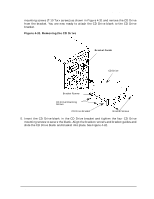 123
123 124
124 125
125 126
126 127
127 128
128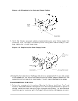 129
129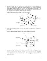 130
130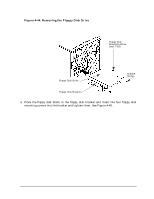 131
131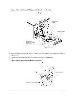 132
132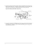 133
133