HP Visualize b160L hp Visualize workstation b132L and b160L service handbook ( - Page 36
Serial I/O Connectors
 |
View all HP Visualize b160L manuals
Add to My Manuals
Save this manual to your list of manuals |
Page 36 highlights
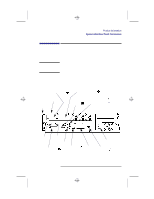
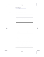
Chap1.doc 14 Thu Jul 25 10:22:00 1996 Table 2 Product Information System Unit Rear Panel Connectors Serial I/O Connectors You can attach a variety of pointing devices (such as a mouse or trackball), or peripheral devices to the Serial Input/Output (SIO) ports on the B132L/B160L workstation. Peripheral devices include printers, plotters, modems, and scanners. Consult the documentation that accompanies each pointing or peripheral device for specific information concerning its use. The SIO ports are programmable. You can set functions such as bit rate, character length, parity, and stop bits. The SIO ports are used as an interface for serial asynchronous devices to the CPU. The ports operate at up to a 460.8K baud rate. Table 2 shows the SIO connector pin listings. The serial connectors are 9-pin D-sub connectors. Signal names are those specified in the EIA RS-232 standard. Serial I/O Pins Pin No. Signal Description 1 DCD Data Carrier Detect 2 RXD Receive Data 3 TXD Transmit Data 4 DTR Data Terminal Ready 5 GND Ground 6 DSR Data Set Ready 7 RTS Request To Send 8 CTS Clear To Send 9 RI Ring Indicator 14
-
 1
1 -
2
-
3
-
4
-
5
-
6
-
7
-
8
-
9
-
10
-
11
-
12
-
13
-
14
-
15
-
16
-
17
-
18
-
19
-
20
-
21
-
22
-
23
-
24
-
25
-
26
-
27
-
28
-
29
-
30
-
 31
31 -
 32
32 -
 33
33 -
 34
34 -
 35
35 -
 36
36 -
 37
37 -
 38
38 -
 39
39 -
 40
40 -
 41
41 -
42
-
43
-
44
-
45
-
46
-
47
-
48
-
49
-
50
-
51
-
52
-
53
-
54
-
55
-
56
-
57
-
58
-
59
-
60
-
61
-
62
-
63
-
64
-
65
-
66
-
67
-
68
-
69
-
70
-
71
-
72
-
73
-
74
-
75
-
76
-
77
-
78
-
79
-
80
-
81
-
82
-
83
-
84
-
85
-
86
-
87
-
88
-
89
-
90
-
91
-
92
-
93
-
94
-
95
-
96
-
97
-
98
-
99
-
100
-
101
-
102
-
103
-
104
-
105
-
106
-
107
-
108
-
109
-
110
-
111
-
112
-
113
-
114
-
115
-
116
-
117
-
118
-
119
-
120
-
121
-
122
-
123
-
124
-
125
-
126
-
127
-
128
-
129
-
130
-
131
-
132
-
133
-
134
-
135
-
136
-
137
-
138
-
139
-
140
-
141
-
142
-
143
-
144
-
145
-
146
-
147
-
148
-
149
-
150
-
151
-
152
-
153
-
154
-
155
-
156
-
157
-
158
-
159
-
160
-
161
-
162
-
163
-
164
-
165
-
166
-
167
-
168
-
169
-
170
-
171
-
172
-
173
-
174
-
175
-
176
-
177
-
178
-
179
-
180
-
181
-
182
-
183
-
184
-
185
-
186
-
187
-
188
-
189
-
190
-
191
-
192
-
193
 |
 |