HP Xw6600 HP Workstations - HP eSATA PCI cable kit installation - Page 3
Accessing the internal components of the workstation, Removing components
 |
UPC - 883585731121
View all HP Xw6600 manuals
Add to My Manuals
Save this manual to your list of manuals |
Page 3 highlights
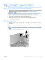
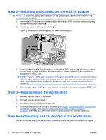
Step 1-Preparing for component installation NOTE: Workstation models vary. All illustrations are examples only. Accessing the internal components of the workstation 1. If you need help preparing the workstation for this installation, consult the removal and replacement procedures in the service guide for your workstation at http://www.hp.com/support/ workstation_manuals. NOTE: For the HP Workstation series, these procedures are also available in the User Guide on the Documentation and Diagnostics CD that shipped with your workstation. 2. Power down the workstation, and then disconnect the power cord. 3. Power down all external devices, and then disconnect them from the workstation. 4. Remove the side access panel. Removing components 1. If present, remove the card support to enable access to the expansion slots and system board connectors. 2. Select an available expansion slot or mechanical bulkhead slot and remove the slot cover. The eSATA adapter can be installed in any unused slot. NOTE: To identify an available PCIe expansion slot, see the service label on the side access panel. Figure 1 Removing the expansion slot cover ENWW Step 1-Preparing for component installation 3
-
 1
1 -
 2
2 -
 3
3 -
 4
4 -
 5
5 -
 6
6
 |
 |