HP Xw8400 SAS Rear panel cable installation
HP Xw8400 - Workstation - 4 GB RAM Manual
 |
UPC - 883585271085
View all HP Xw8400 manuals
Add to My Manuals
Save this manual to your list of manuals |
HP Xw8400 manual content summary:
- HP Xw8400 | SAS Rear panel cable installation - Page 1
cable with mounting screw ■ SAS rear panel mounting bracket ■ External SAS label ■ SAS rear panel cable instruction (this document) ■ Warranty Before you begin See http://www.hp.com/accessories/workstations to determine the compatibility of this product with your HP workstation. Observe warnings and - HP Xw8400 | SAS Rear panel cable installation - Page 2
includes instructions for disassembling and preparing the workstation for installation, including shutting down power, disconnecting all power from the system, and removing the access panel. For more detailed information, refer to the Service and Technical Reference Guide for your HP Workstation at - HP Xw8400 | SAS Rear panel cable installation - Page 3
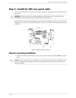
cables to the SATA connectors. Connect the SAS rear panel cables to the SAS connectors only or the hard drives will not function. Locate the SAS connectors by reviewing the system board layout illustration on the service label of your workstation access panel. The following illustration is shown - HP Xw8400 | SAS Rear panel cable installation - Page 4
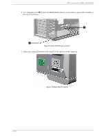
panel cable installation 2. Use a mounting screw 2 to attach the MiniSAS 4X connector of the SAS rear panel cable assembly to the rear of the chassis. 1 2 Figure 2 Attach MiniSAS 4X connector 3. Adhere the external SAS label to the outside of the chassis near the connector. Figure 3 Adhere label to - HP Xw8400 | SAS Rear panel cable installation - Page 5
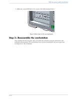
4X connector of the SAS rear panel cable assembly to the SAS mounting bracket 1. Install the SAS mounting bracket in the workstation in place of the PCI slot cover 2. Connect the SAS cables to the SAS connectors on the system board 3, or to an approved, compatible plug in card. (Refer to Before you - HP Xw8400 | SAS Rear panel cable installation - Page 6
to SAS mounting bracket Step 3-Reassemble the workstation After installing the SAS rear panel cable, reassemble the workstation using the instructions in the workstation documentation. The reassembly process involves reinstalling the side access panel and restoring power to the workstation. 6/12 - HP Xw8400 | SAS Rear panel cable installation - Page 7
SAS SAS HP xw Series Workstation HP Workstation SAS (Serial Attached SCSI SAS SAS SAS SAS HP Workstation http://www.hp.com/accessories/workstations 7/12 - HP Xw8400 | SAS Rear panel cable installation - Page 8
SAS Å Å Safety & Comfort Guide http://www.hp.com/ergo CD HP HP Workstation 1 http://www.hp.com/support/workstation_manuals HP Workstation の 『Service and Technical Reference Guide 8/12 - HP Xw8400 | SAS Rear panel cable installation - Page 9
SAS 2 - SAS SAS Ä 注意 : SAS SATA SAS SAS SAS SAS 図 1 1. SAS SAS SAS 1 SAS 4 9/12 - HP Xw8400 | SAS Rear panel cable installation - Page 10
SAS 2 2 SAS MiniSAS 4X コ ネ ク 1 2 図 2 MiniSAS 4X 3. 外部 SAS 図 3 10/12 - HP Xw8400 | SAS Rear panel cable installation - Page 11
SAS SAS 1 PCI PCI 1 PCI PCI 2 参照 )。 図 4 PCI 2. SAS MiniSAS 4X SAS 1 SAS PCI 2 SAS SAS 3 図 5 SAS 11/12 - HP Xw8400 | SAS Rear panel cable installation - Page 12
SAS 3. 外部 SAS SAS 図 6 SAS 3 SAS 416482-002 © 2006 Hewlett-Packard Development Company, L.P. The HP Invent logo is a registered trademark of Hewlett-Packard Development Company, L.P. 12/12
-
 1
1 -
 2
2 -
 3
3 -
 4
4 -
 5
5 -
 6
6 -
 7
7 -
8
-
9
-
10
-
11
-
12
 |
 |
1/
12
SAS rear panel cable installation
SAS Rear panel cable installation
HP xw series workstations
This document describes how to install the Serial Attached SCSI (SAS) rear panel cable to your HP
workstation.
Kit contents
This kit includes the following components:
■
SAS rear panel cable with mounting screw
■
SAS rear panel mounting bracket
■
External SAS label
■
SAS rear panel cable instruction (this document)
■
Warranty
Before you begin
to determine the compatibility of this product with your
HP workstation.
Observe warnings and cautions
Å
WARNING:
Any surface or area of the equipment marked with these symbols indicates the presence of
a hot surface or hot component. If this surface is contacted, the potential for injury exists. To reduce the
risk of injury from a hot component, allow the surface to cool before touching.
Å
WARNING:
Any surface or area of the equipment marked with these symbols indicates the presence of
an electrical shock hazard. To reduce the risk of injury from electrical shock, do not open any enclosed
area.