HP d230 HP Compaq Business Desktop d220 MT, d230 MT, d228 MT Computers Illustr - Page 2
Before exiting, click Save Settings and Exit. - bios
 |
View all HP d230 manuals
Add to My Manuals
Save this manual to your list of manuals |
Page 2 highlights
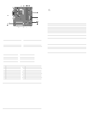
System Board Connectors and Jumpers (position of some untitled components may vary in location) BAT1 Real-time-clock battery CMOS CMOS Reset button DIMM1 Memory socket 1 DIMM2 Memory socket 2 J11 Aux in audio J12 CD in audio J13 Wake on LAN J17 System fan J20 Front side USB J21 CPU fan #See table below AGP socket not shown in this drawing J25 Secondary IDE connector J27 Power/LED switch J28 Primary IDE connector J29 ATX Main power J31 Diskette drive connector J35 Chassis fan JP1# Processor safe mode JP2# Boot Block U13 Processor socket JP1 Status Normal Safe Recovery Jumper Setting 1-2 2-3 Open Notes Default JP2 Status Lock Unlock Jumper Setting 1-2 2-3 Notes Default System Hardware Interrupts IRQ System Function 0 Timer Interrupt 1 Keyboard 2 Interrupt Controller Cascade 3 Serial Port (COM B) 4 Serial Port (COM A) 5 Unused, available for PCI 6 Diskette Drive 7 Parallel Port (LPT 1) IRQ System Function 8 Real-Time Clock 9 Unused 10 Unused, available for PCI 11 Unused, available for PCI 12 Mouse 13 Coprocessor 14 Primary ATA (IDE) Controller 15 Secondary ATA (IDE) Controller Establishing a Password 1. Turn on or restart the computer. If you are in Windows, click Start > Shut Down > Restart the computer. 2. When the F10 Setup message appears in the lower-right corner of the screen, press the F10 key. Press Enter to bypass the title screen, if necessary. If you do not press F10 when prompted, a restart will be necessary. 3. Select Password Option, then select Change Supervisor Password and follow the instructions on the screen. You may also want to establish the Password check at this time. This will allow you to specify when the password will be required. 4. Before exiting, click Save Settings and Exit. Changing a Password 1. Turn on or restart the computer. If you are in Windows, click Start > Shut Down > Restart the Computer. To change the setup password, run Computer Setup. 2. When the key icon appears, type your current password, a slash (/) or alternate de-limiter character, your new password, another slash (/) or alternate delimiter character, and your new password again as shown: current password/new password/new password. NOTE: Type the new password carefully since the actual characters do not appear on the screen. 3. Press the enter key. 4. The new password will take effect the next time the computer is restarted. Deleting a Password 1. Turn on or restart the computer. If you are in Windows, click Start > Shut Down > Restart the Computer. To delete the setup password, run Computer Setup (F10). 2. When the key icon appears, type your current password followed by a slash (/) or alternate delimiter character as shown. Example: currentpassword/ 3. Press the Enter key. Clearing CMOS* The computer's configuration (CMOS) may occasionally be corrupted. If it is, it is necessary to clear the CMOS memory using by performing the following procedure: Ä CAUTION: The power cord must be disconnected from the power source before changing the jumper setting. (NOTE: All LEDs on the board should be OFF). Failure to do so may damage the system board 1. Turn off the computer and any external devices, then disconnect the power cord from the power outlet. 2. Remove the access panel. 3. Locate the switch CMOS and press the button, holding it down for 5 seconds. 4. Replace the access panel. 5. Connect the power cord to the power outlet. 6. Turn on the computer, allow it to start. NOTE: Clearing CMOS clears all passwords. Diagnostic LEDs LED Power Power Power Power Power Power Color Green Green Green Clear Clear Red/Green Power Red Power Red Power Red Power Red Hard Drive Green LED Activity State/Message On (S0) Computer on 1 blink every 2 seconds (S1) Normal Suspend Mode 1 blink every 2 seconds (S3) Suspend to RAM Off (S4) Suspend to Disk (if applicable) Off (S5) Computer off Red when flashing ROM; Green 1 blink every second when user can restart Boot block recovery w/Embedded Video 1 blink every second for 2 seconds CPU thermal shutdown 1 blink every second for 5 No memory installed seconds, then 2 second pause. 5 beeps. 1 blink every second for 6 sec- Graphics card error onds, then 2 second pause. 6 beeps. 1 blink every second for 7 System board failure seconds, then 2 second pause. 7 beeps. Blinking Hard drive activity Computer Setup (F10) Utility Features (not all features may be available) System Information Standard CMOS Setup Advanced CMOS Setup Power Management Setup System S/N Product Name System Chipset Type BIOS Version BIOS Release Date Processor Type Processor Speed Set Time Set Date Set Floppy size and capacity Auto Detect Primary IDE Master drive Boot Device Priority Try Other Boot Device POST Delay Time (in seconds) System Keyboard ACPI Standby State Reset on AC/Power Loss Resume on Ring CPU ID L1 Cache Size L2 Cache Size Memory Bank 0 Memory Bank 1 Total Memory Auto Detect Primary IDE Slave drive Auto Detect Secondary IDE Master drive Auto Detect Secondary IDE Slave drive APIC ACPI SCI IRQ Hyper-Threading Technology Internal Graphics Mode Select Resume on LAN Resume on PME Peripheral Setup Hardware Monitor Password Option OnBoard LAN OnBoard LAN Chip Boot ROM Init. Graphics Adapter Priority USB Controller CPU Ratio Selection CPU Warning Temperature CPU Shutdown Temperature System Warning Temperature System Shutdown Temperature CPU Temperature System Temperature CPU FAN Speed Change Supervisor Password Password Status Password Check USB 1.1 Device Legacy Support OnBoard Serial Port OnBoard Parallel Port Chassis FAN Speed CPU VID Vccp +1.5V +2.5V +3.3V +5.0V +12.0V Load Default Settings Save Settings and Exit Exit Without Saving Note: See Computer Setup (F10) Utility Guide on the Documentation Library CD.
-
 1
1 -
 2
2
 |
 |
