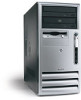
HP d325 HP Business Desktop d325/dx6050 uT Illustrated Parts Map, 3rd Edition - Page 2
Clearing and Setting the Setup and Power-On Passwords - ram
 |
View all HP d325 manuals
Add to My Manuals
Save this manual to your list of manuals |
Page 2 highlights
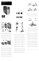
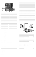
System Board Connectors and Jumpers E49 Password jumper J20 PCI expansion slot 1 J21 PCI expansion slot 2 J22 PCI expansion slot 3 J40 AGP connector P1 Main power connector P3 CPU 12V reg input P5 Power button/LED P6 Internal speaker P7 CD audio P8 Chassis fan P10 Diskette drive P11 Aux audio P20 Primary IDE Interrupts IRQ System Resource 0 Reserved, interval timer 1 Reserved, keyboard buffer full 4 Serial Port (COM 1) 5 PCI system management 6 Diskette drive controller 8 Real-time clock 9 ACPI-compliant system P21 P23 P24 P29 P52 P70 P124 P125 SW3 SW50 XBT1 XMM1 XMM2 XU1 Secondary IDE Audio Front USB SCSI LED Serial port CPU fan Hood lock Hood sensor Safe Mode jumper (default = 1-2) CMOS reset Real-time clock battery Memory Memory Processor IRQ System Resource 12 Onboard mouse port 13 Reserved, numeric data coprocessor 14 Primary IDE controller 15 Secondary IDE controller 19 Integrated graphics (GPU) 21 Integrated audio/USB host controller 22 Network interface card (NIC) Computer Setup (F10) Utility Features (not all features may be available) File Storage Security Advanced System Information About Set Time and Date Save to Diskette Restore From Diskette Set Defaults and Exit Ignore Changes and Exit Save Changes and Exit Device Configuration Storage Options IDE DPS Self-Test Controller Order Boot Order Setup Password Power-On Password Password Options Embedded Security Smart Cover Smart Sensor DriveLock System IDs Master Boot Record Security Save Master Boot Record Restore Master Boot Record Device Security Network Service Boot Power-On Options BIOS Wakeup Onboard devices PCI Devices Bus Options Devise Options PCI VGA Configuration Note: See Computer Setup (F10) Utility Guide on the Documentation Library CD. Clearing CMOS 1. Turn off the computer and any external devices, then disconnect the power cord from the power outlet. 2. Remove the access panel. 3. Locate the switch SW50 and press the button, holding it down for 5 seconds. 4. Replace the access panel. 5. Connect the power cord to the power outlet. 6. Turn on the computer, allow it to start. Clearing and Setting the Setup and Power-On Passwords 1. Turn off the computer and any external devices, then disconnect the power cord from the power outlet. 2. Remove the access panel. 3. Locate the header labeled E49. 4. Move the jumper from pins 1 & 2 to pins 2 & 3. 5. Replace the access panel. 6. Connect the power cord to the power outlet. NOTE: Placing the jumper on pins 2 & 3 and restarting the computer clears the current passwords and disables the password features. 7. To re-enable the password features, repeat steps 1-3, then replace the jumper on pins 1 & 2 (safe position). 8. Repeat steps 5-6, then establish new passwords. NOTE: All passwords will be cleared. Diagnostic LEDs LED Power Power Power Power Power Power Color Green Green Green Clear Clear Red/Green Power Power Power Power Power Power Hard Drive Red Red Red Red Red Red Green LED Activity State/Message On (S0) Computer on 1 blink every 2 seconds (S1) Normal Suspend Mode 1 blink every 2 seconds (S3) Suspend to RAM Off (S4) Suspend to Disk (if applicable) Off (S5) Computer off Red when flashing ROM; Green 1 blink every second when user can restart Boot block recovery w/Embedded Video 3 blinks 1 every second, then 2 CPU not installed second pause 4 blinks 1 every second, then 2 CPU thermal shutdown second pause 5 blinks 1 every second, then 2 Memory error second pause. 5 Beeps 6 blinks 1 every second, then 2 Graphics error second pause.6 Beeps 7 blinks 1 every second, then 2 System board failure second pause. 7 Beeps 8 blinks 1 every second, then 2 Invalid ROM second pause. 8 Beeps Blinking Hard drive activity Keyboard Diagnostic LEDs LED Color LED Activity State/Message Num, Caps, Scroll Lock Green Flash On-Off 2 times (Beeps - Invalid system ROM detected. ROM forces 1L, 3S) reflash. Num, Caps, Scroll Lock Green On (Rising Tone) ROM reflashed successfully Num Lock Green On ROMPaq diskette not present, is bad, or drive not ready.* Caps Lock Green On Enter password. Num, Caps, Scroll Lock Green Blink On in sequence, one at a Keyboard locked in network mode time - N, C, SL * Insert valid ROMPaq diskette in drive A. Turn power switch off, then on to reflash ROM. If ROM flash is successful, all three keyboard LEDs will light up, and you will hear a rising tone series of beeps. Remove diskette and turn power off, then on to restart the computer. For more information about flashing the ROM, refer to the Troubleshooting guide. Heatsink Removal Keyboards (not illustrated) Easy Access Keyboard, PS/2 323686-001-xxx 324634-001-xxx Europe* -021 International** -B31 Thai French Canadian -121 Latin American Spanish -161 U.S. Japanese -291 People's Republic of China -AA1 Korean (Hanguel) -AD1 Taiwanese -AB1 *For 324634-xxx keyboard only **For 323686-xxx keyboard only Keyboard, Wireless French Canadian Japanese Korean (Hanguel) 323745-xxx -121 International -B31 -291 Latin American Spanish -161 -AD1 People's Republic of China -AA1 Taiwanese Thai U.S. Smartcard, Easy Access Keyboard, USB French Canadian -121 Japanese -291 Korean (Hanguel) -AD1 323746-xxx International -B31 Latin American Spanish -161 People's Republic of China -AA1 Taiwanese Thai U.S. Keyboard, Basic, USB Keyboard, Basic, PS/2 355631-xxx 355630-xxx French Canadian -121 Latin American Spanish -161 U.S. -281 -001 -AB1 -281 -001 -AB1 -281 -001 -001
-
 1
1 -
 2
2
 |
 |
