HP dv8000 Maintenance and Service Guide - Page 114
LED Board, LED Board Spare Part Number Information
 |
UPC - 654954100226
View all HP dv8000 manuals
Add to My Manuals
Save this manual to your list of manuals |
Page 114 highlights
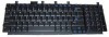
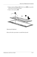
Removal and Replacement Procedures 5.12 LED Board LED Board Spare Part Number Information LED board (includes LED board cable) 403833-001 1. Prepare the computer for disassembly (Section 5.3) and then remove the following components: a. Memory/Mini PCI module compartment cover (Section 5.6) b. Switch cover (Section 5.10) c. Keyboard assembly frame (Section 5.11) 2. Turn the keyboard assembly frame upside down with the LED board toward you. 5-28 Maintenance and Service Guide
-
 1
1 -
2
-
3
-
4
-
5
-
6
-
7
-
8
-
9
-
10
-
11
-
12
-
13
-
14
-
15
-
16
-
17
-
18
-
19
-
20
-
21
-
22
-
23
-
24
-
25
-
26
-
27
-
28
-
29
-
30
-
31
-
32
-
33
-
34
-
35
-
36
-
37
-
38
-
39
-
40
-
41
-
42
-
43
-
44
-
45
-
46
-
47
-
48
-
49
-
50
-
51
-
52
-
53
-
54
-
55
-
56
-
57
-
58
-
59
-
60
-
61
-
62
-
63
-
64
-
65
-
66
-
67
-
68
-
69
-
70
-
71
-
72
-
73
-
74
-
75
-
76
-
77
-
78
-
79
-
80
-
81
-
82
-
83
-
84
-
85
-
86
-
87
-
88
-
89
-
90
-
91
-
92
-
93
-
94
-
95
-
96
-
97
-
98
-
99
-
100
-
101
-
102
-
103
-
104
-
105
-
106
-
107
-
108
-
 109
109 -
 110
110 -
 111
111 -
 112
112 -
 113
113 -
 114
114 -
 115
115 -
 116
116 -
 117
117 -
 118
118 -
 119
119 -
120
-
121
-
122
-
123
-
124
-
125
-
126
-
127
-
128
-
129
-
130
-
131
-
132
-
133
-
134
-
135
-
136
-
137
-
138
-
139
-
140
-
141
-
142
-
143
-
144
-
145
-
146
-
147
-
148
-
149
-
150
-
151
-
152
-
153
-
154
-
155
-
156
-
157
-
158
-
159
-
160
-
161
-
162
-
163
-
164
-
165
-
166
-
167
-
168
-
169
-
170
-
171
-
172
-
173
-
174
-
175
-
176
-
177
-
178
-
179
-
180
-
181
-
182
-
183
-
184
-
185
-
186
-
187
-
188
-
189
-
190
-
191
-
192
-
193
-
194
-
195
-
196
-
197
-
198
-
199
-
200
-
201
-
202
-
203
-
204
-
205
-
206
-
207
-
208
-
209
-
210
-
211
-
212
-
213
-
214
-
215
-
216
-
217
-
218
-
219
-
220
-
221
-
222
-
223
-
224
-
225
-
226
-
227
-
228
-
229
-
230
-
231
-
232
-
233
-
234
-
235
-
236
-
237
-
238
-
239
-
240
-
241
-
242
-
243
-
244
-
245
-
246
 |
 |

5–28
Maintenance and Service Guide
Removal and Replacement Procedures
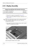
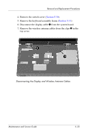
5.12
LED Board
1. Prepare the computer for disassembly (
Section 5.3
) and then
remove the following components:
a.
Memory/Mini PCI module compartment cover
(
Section 5.6
)
b.
Switch cover (
Section 5.10
)
c.
Keyboard assembly frame (
Section 5.11
)
2. Turn the keyboard assembly frame upside down with the
LED board toward you.
LED Board Spare Part Number Information
LED board (includes LED board cable)
403833-001