HP dx2200 HP Compaq Business Desktop dx2200 Microtower - Illustrated Parts Map - Page 2
Save & Exit Setup - ram
 |
View all HP dx2200 manuals
Add to My Manuals
Save this manual to your list of manuals |
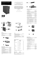
Page 2 highlights
System Board Connectors and Jumpers (position of some untitled components may vary in location) ATX1 AUD1 BATTERY CPU FAN DIMM1 DIMM2 FDD1 IDE1 JCD1 JCMOS JPFP1 JPW1 Main power Front audio RTC battery Processor fan Memory module 1 Memory module 2 Diskette drive Optical drive CD audio CMOS Front power switch/LED CPU main power JUSB1 JUSB2 PCIE16X1 PCIE1X1 PCI1 PCI2 SATA1 SATA2 SPKR SYSFAN1 U4 Front USB Internal USB for media reader PCIe X16 PCIe X1 PCI slot 1 PCI slot 2 SATA primary SATA secondary speaker Chassis fan Processor CMOS Status Normal Clear Jumper Setting 2-3 1-2 Notes Default leave on for 5 seconds System Hardware Interrupts IRQ System Function 0 Timer Interrupt 1 Keyboard 2 Interrupt Controller Cascade 3 Serial Port (COM B) 4 Serial Port (COM A) 5 Unused, available for PCI 6 Diskette Drive 7 Parallel Port (LPT 1) IRQ System Function 8 Real-Time Clock 9 Unused 10 Unused, available for PCI 11 Unused, available for PCI 12 Mouse 13 Coprocessor 14 Primary ATA (IDE) Controller 15 Secondary ATA (IDE) Controller Clearing CMOS The computer's configuration (CMOS) may occasionally be corrupted. If it is, it is necessary to clear the CMOS memory using by performing the following procedure: Ä CAUTION: The power cord must be disconnected from the power source before changing the jumper setting. (NOTE: All LEDs on the board should be OFF). Failure to do so may damage the system board 1. Turn off the computer and any external devices, then disconnect the power cord from the power outlet. 2. Remove the access panel. 3. Locate jumper CMOS and move the jumper from pins 2-3 to pins 1-2. 4. Leave the jumper on pins 1-2 for 5 seconds. 5. Move the jumper back to pins 2-3. 6. Replace the access panel. 7. Connect the power cord to the power outlet. 8. Turn on the computer, allow it to start. Diagnostic LEDs LED Power Power Power Power Power Color Green Green Green Clear Green Power Green Power Green None None Hard Drive None None Green LED Activity State/Message On Computer on 1 blink every 2 seconds (S1) Normal Suspend Mode 1 blink every 2 seconds (S3) Suspend to RAM Off (S5) Computer off Glows for 3 seconds followed by CPU thermal shutdown a 1 second pause. 1 blink every second for 5 No memory installed or improperly installed seconds, then 2 second pause. (pre-video memory error) 5 beeps. 1 blink every second for 6 Graphics card error (pre-video graphics error) seconds, then 2 second pause. 6 beeps. No LED but rapidly inclining Incorrect system password. beeps No LED but rapidly declining Correct system password. beeps Blinking Hard drive activity Computer Setup (F10) Utility Features (not all features may be available) System Information Standard CMOS Features Advanced BIOS Features Advanced Chipset Features Integrated Peripherals Power Management Setup PnP/PCI Configuration PC Health Status Product Name SKU Number Processor Type Processor speed CPU ID/Patch ID Cache Size Memory Size System ROM Integrated MAC Address UUID System Serial Number Asset Tracking Number Asset Tag Number Set Date Set Time PATA Controller PATA Channel 0 Master PATA Channel 0 Slave SATA Controller SATA Channel 1 Master SATA Channel 2 Master Floppy Drive Controller Drive A Halt On POST Delay Device Boot Disabling F9 Boot Menu Removable Device Boot Priority Hard Disk Boot Sequence Optical Drive Boot Sequence Network Boot Sequence First through Fourth Boot Devices Boot Up NumLock Status Security Option APIC Mode MPS Version Control for OS BIOS Write Protection Execute disable bit Enhanced Intel SpeedStep Technology Hyper-Threading Technology UMA Frame Buffer Init Display First (VGA Setting) Surroundview AutoDetect PCI CLK (VGA Setting) Onboard HD Audio OnChip USB Controller USB Legacy Support Onboard LAN Onboard LAN Boot ROM Onboard Serial Port Onboard Parallel Port Parallel Port Mode ECP Mode Use DMA After AC Power Loss ACPI Suspend type External Modem S5 Wake-up RTC Alarm Resume Date (of Month) Alarm Resume Time (hh:mm:ss) Reset Configuration Data Resources Controlled By IRQ Resources Maximum Payload Size System Fan Fail Check Smart Fan Function Current CPU Temperature Current System Temperature Current CPU Fan Speed Current System Fan Speed Vcore +12V VCC5 +3.3V VBAT (V) 3VSB (V) Load Optimized Defaults Set Supervisor Password Set User Password Save & Exit Setup Exit Without Saving Note: See Computer Setup (F10) Utility Guide on the Documentation Library CD.
-
 1
1 -
 2
2
 |
 |
