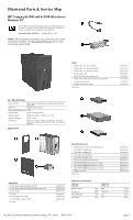
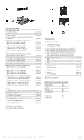
HP dx2308 HP Compaq dx2300 and dx2308 Microtower Business PC, Illustrated Part - Page 4
Failsafe Boot Block ROM, Password Security, Diagnostic Functions, Error Conditions and Messages - drivers
 |
View all HP dx2308 manuals
Add to My Manuals
Save this manual to your list of manuals |
Page 4 highlights
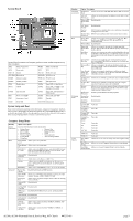
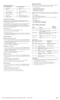
System Hardware Interrupts IRQ System Function 0 Timer Interrupt 1 Keyboard 2 Interrupt Controller Cascade 3 Serial Port (COM B) 4 Serial Port (COM A) 5 Unused, available for PCI 6 Diskette Drive 7 Parallel Port (LPT 1) IRQ System Function 8 Real-Time Clock 9 Unused 10 Unused, available for PCI 11 Unused, available for PCI 12 Mouse 13 Coprocessor 14 Primary ATA (IDE) Controller 15 Secondary ATA (IDE) Controller Failsafe Boot Block ROM The computer comes with a reprogrammable flash system ROM (read only memory). To upgrade the ROM, download the latest ROM BIOS image from the HP Web site (www.hp.com) and follow the online GUI/instructions. Your system ROM includes a Failsafe Boot Block that is protected during the flash process and allows the computer to be restarted in the unlikely event of an unsuccessful ROM flash. If the system detects an invalid system ROM during the boot sequence, the Failsafe Boot Block attempts to locate a valid BIOS image on removable media. To recover from the Boot Block recovery mode complete the following steps: Boot Block Recovery 1. Remove any bootable media from the computer and turn off power. 2. Insert a flash drive or CD containing the ROM BIOS. 3. Turn on power to the system. 4. The system will automatically flash the ROM. After a successful flash, the system will either automatically restart or prompt the user to unplug the unit, wait 5 seconds, reattach the power cord, and then press the power button. Password Security Establishing a Supervisor Password: 1. Turn on or restart the computer. If you are in Windows, click Start > Shut Down > Restart. 2. As soon as the computer is turned on, press F10 when the monitor light turns green to enter Computer Setup. Press Enter to bypass the title screen, if necessary. If you do not press F10 when prompted, a restart will be necessary. 3. Select Boot > Setup Supervisor Password and follow the instructions on the screen. 4. Before exiting, click File > Save and Exit Setup. Establishing a User Password: 1. Turn on or restart the computer. If you are in Windows, click Start > Shut Down > Restart. 2. As soon as the computer is turned on, press F10 when the monitor light turns green to enter Computer Setup. Press Enter to bypass the title screen, if necessary. If you do not press F10 when prompted, a restart will be necessary. 3. Select Boot > Set User Password and follow the instructions on the screen. Before exiting, click File > Save and Exit Setup. Changing a Password: 1. Turn on or restart the computer. If you are in Windows, click Start > Shut Down > Restart. 2. As soon as the computer is turned on, press F10 when the monitor light turns green to enter Computer Setup. 3. When the key icon appears, type your current password. 4. Select Boot > Set Supervisor (or user) Password. 5. Enter the new password (or nothing for no password) in the key icon and press Enter. The new password will take effect the next time the computer is restarted. Deleting a Password 1. Turn on or restart the computer. If you are in Windows, click Start> Shut Down > Restart. 2. As soon as the computer is turned on, press F10 when the monitor light turns green to enter Computer Setup. 3. When the key icon appears, type your current password. 4. Select Boot > Set Supervisor (or user) Password. 5. Enter nothing for no password in the key icon and press Enter. The new password will take effect the next time the computer is restarted. Diagnostic Functions Diagnostic functions are provided by the Setup Utility (in system ROM) and by Insight Diagnostics. Insight Diagnostics provides detailed system information including: • Processor type and speed • Memory amount, mapping, and integrity • Hardware peripheral availability/settings • Hard drive type, space used/available • System identification, asset tracking Insight Diagnostics may be found on the Documentation and Diagnostics CD that shipped with the computer. The tool may also be downloaded from the hp Web site using the following procedure: 1. Go to www.hp.com 2. Click the Software and Download driver link. 3. Enter the product number (for example, dx2250) in the text box and press the Enter key. 4. Select the specific product. 5. Select the OS. 6. Click the Diagnostics link. 7. Select HP Insight Diagnostics Offline Edition. 8. Select the proper language and click Download. Error Conditions and Messages Feature Purpose How It Is Established Floppy drive controller Prevents the transfer of data to or from the Setup Utilities floppy drive. Device Boot Disabling Prevents booting from and or all of these devices: Internal or external USB, Internal ODD, or Internal FDD. Setup Utilities Security Option Prevents use of computer until password is Setup Utilities entered. Can apply to both initial startup and restart. BIOS Write Protect Restricts ability to change ROM BIOS with- Setup Utilities. out approval. USB Controller Allows you to disable or enable all USB devices. Setup Utilities Diagnostic LEDs LED Color LED Activity State/Message Power Green On Computer on Power Green 1 blink every 2 seconds Suspend to RAM (some models) Power Green 1 blink every second CPU thermal shutdown Power Green 5 blinks, 1 blink every second Pre-video memory error followed by 1 short beep Power Green 6 blinks, 1 blink every second Pre-video graphics error followed by a 1 long and 2 short beeps Power Green 8 blinks, 1 blink every second Invalid ROM based on Checksum with followed by 2 short beeps FDD installed Power Green 8 blinks, 1 blink every second Invalid ROM based on Checksum withfollowed by 2 short beeps and out FDD installed hurried beeps none none System does not power on and System unable to power on LEDs are not flashing Clearing CMOS 1. Turn off the computer and any external devices, disconnect the power cord from the power outlet, and remove the access panel. 2. Locate jumper JBAT1 and move the jumper from pins 2-3 to pins 1-2. 3. Leave the jumper on pins 1-2 for 5 seconds then, move the jumper back to pins 2-3. 4. Replace the access panel and connect the power cord to the power outlet. 5. Turn on the computer, allow it to start. dx2300, dx2308 Illustrated Parts & Service Map, MT Chassis 443233-001 page 4
-
 1
1 -
 2
2 -
 3
3 -
 4
4
 |
 |