HP dx2310 Illustarted Parts Map: HP Compaq Business Desktop dx2310/dx2318 Micr - Page 2
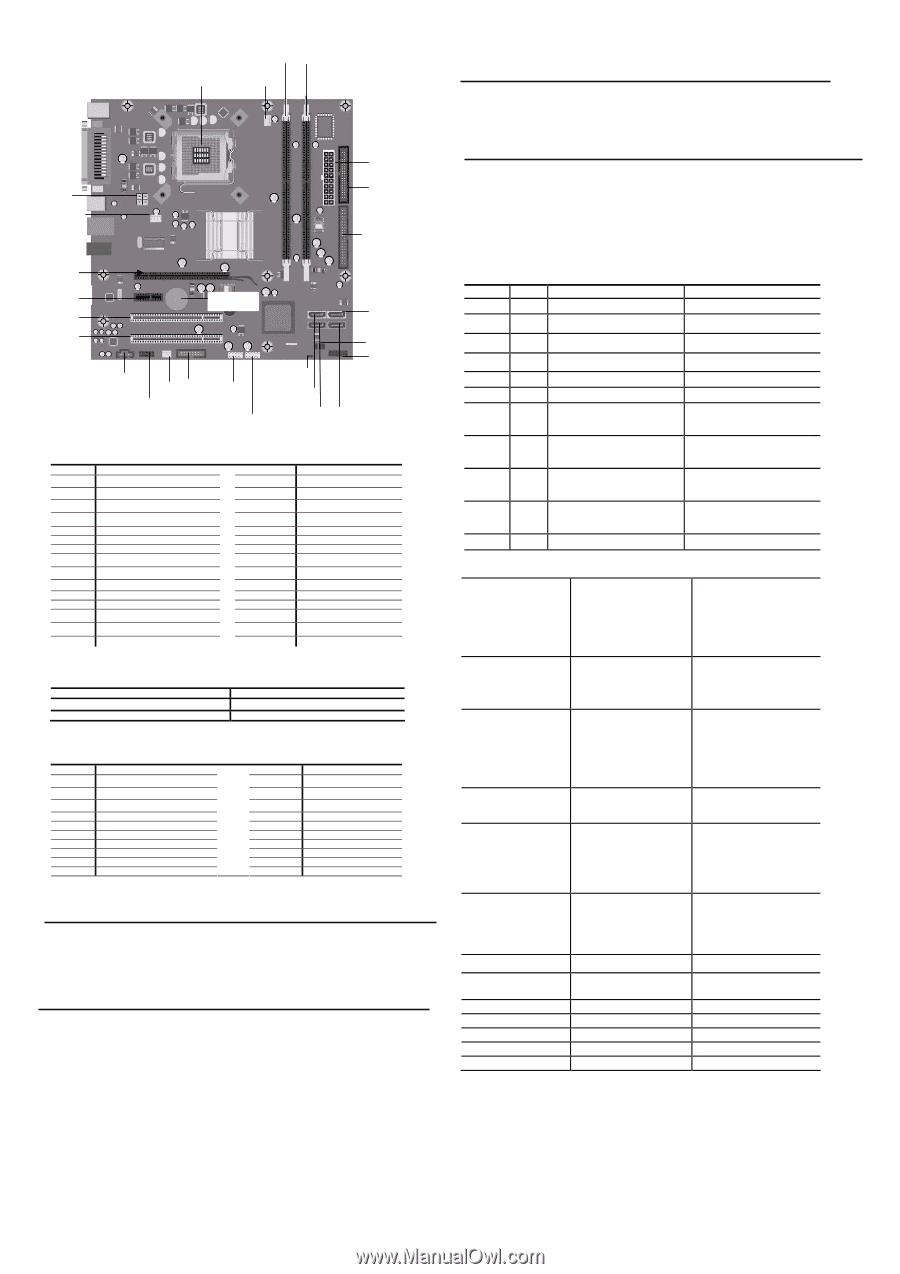
Dimm1, Dimm 2, Cpu Xu1, Cpu_fan, Sys_fan, Pcie X 1, Pci 1, Pci 2, Pcie X 16, Front, Panel Header, - computers
 |
View all HP dx2310 manuals
Add to My Manuals
Save this manual to your list of manuals |
Page 2 highlights
DIMM1 DIMM 2 CPU XU1 CPU_FAN Deleting a Password 1. Turn on or restart the computer. If you are in Windows, click Start > Shut Down > Restart the Computer. To delete the setup password, run Computer Setup (F10). 2. When the key icon appears, type your current password followed by a slash (/) or alternate delimiter character as shown. Example: currentpassword/ 3. Press the Enter key. Clearing CMOS* P5 SYS_FAN PWR P3 FLOPPY IDE The computer's configuration (CMOS) may occasionally be corrupted. If it is, it is necessary to clear the CMOS memory using by performing the following procedure:: △ CAUTION: The power cord must be disconnected from the power source before changing the jumper setting. (NOTE: All LEDs on the board should be OFF). Failure to do so may damage the system board 1. Turn off the computer and any external devices, then disconnect the power cord from the power outlet. 2. Remove the access panel. 3. Clear CMOS with header E17. 4. Replace the access panel. 5. Connect the power cord to the power outlet. 6. Turn on the computer, allow it to start. NOTE: Clearing CMOS clears all passwords. PCIE X 16 PCIE X 1 PCI 1 XBT1 SATA1 Diagnostic LEDs and Beeps LED Color LED/Beep Activity Power Green On Power Green 1 blink every 2 seconds State/Message (S0) Computer on (S1) Normal Suspend Mode PCI 2 CD_IN P7 J99 P98 P24 P25 E15 SATA3 E16 J18 FRONT PANEL HEADER SATA0 SATA2 Power Power Power Power Power Green Clear Clear Green Red 1 blink every 2 seconds (S3) Suspend to RAM Off (S4) Suspend to Disk (if applicable) Off Green when flashing ROM CPU Fan weak (RPM < 1000) or not turning, Display Warning message and Long Beep for 5 sec and shut down. (S5) Computer off Boot block recovery w/Embedded Video CPU thermal shutdown (Weak CPU fan speed or not running) System Board Connectors and Jumpers (position of some untitled components may vary in location) Label Component Label Component XU1 Processor socket E15 Clear CMOS jumper CPU_FAN CPU fan J18 Front panel header DIMM1 Memory socket 1 XBT1 Real-time-clock battery DIMM2 Memory socket 2 P98 Front audio header IDE FLOPPY PWR P3 SATA0 IDE drive connector Diskette drive connector ATX main power SATA connector 0 CD_IN PCI 1 PCI 2 PCIE X 16 CD in audio PCI 1 connector PCI 2 connector PCI-E X 16 connector SATA1 SATA connector 1 PCIE X 1 PCI-E x1 connector SATA2 SATA3 P24 P25 SATA connector 2 SATA connector 3 FRONT USB 1 FRONT USB 2 SYS_FAN P5 J99 P7 System fan CPU 4 pin power connector 2ND SERIAL PORT HEADER Internal speaker header E16 BOOT BLOCK HEADER Clear_CMOS* Clear CMOS CMOS 1-2 Normal (Default) 2-3 *: clear CMOS function only can be available when system is power off (power cord is disconnected) System Hardware Interrupts IRQ System Function 0 Host controller 1 Keyboard 3 Serial port 1 4 Serial Port 2 4 Parallel Port (LPT 1) 5 UHCI(D29:F2) 6 FDC controller 9 UHCI(D29:F0) 9 EHCI(D29:F7) 9 ACPI Controller IRQ System Function 10 VGA Controller 10 UHCI(D29:F3) 10 HDA controller 11 LAN controller 12 Mouse 14 IDE Controller 15 UHCI(D29:F1) 15 SATA controller 15 SMBUS Controller Establishing a Password 1. Turn on or restart the computer. If you are in Windows, click Start > Shut Down >Restart the computer. 2. When the F10 Setup message appears in the lower-right corner of the screen, press the F10 key. Press Enter to bypass the title screen, if necessary. If you do not press F10 when prompted, a restart will be necessary. 3. Select supervisor password and press enter key, and follow the instructions on the screen. You may also want to establish the Password check at this time. This will allow you to specify when the password will be required. 4. Before exiting, click Save Settings and Exit. Changing a Password 1. Turn on or restart the computer. If you are in Windows, click Start > Shut Down > Restart the Computer. To change the setup password, run Computer Setup. 2. When the key icon appears, type your current password, a slash (/) or alternate de-limiter character, your new password, another slash (/) or alternate delimiter character, and your new password again as shown: current password/new password/new password. NOTE: Type the new password carefully since the actual characters do not appear on the screen.. 3. Press the enter key. 4. The new password will take effect the next time the computer is restarted. Power Red Power Red Power Red Hard Drive Green Power LED flashes 5 seconds every 1 second, followed by 2 seconds pause, and meanwhile, 5 beeps are heard Power LED flashes 6 seconds every 1 second, followed by 2 seconds pause, and meanwhile, 6 beeps are heard Power LED flashes 8 seconds every 1 second, followed by 2 seconds pause, and meanwhile, 8 beeps are heard Blinking No memory installed / Pre-Video memory error Graphics card error (Pre-Video graphics error) System board failure or invalid ROM basing on checksum. Hard drive activity Computer Setup (F10) Utility Features (not all features may be available) System Information Standard CMOS Features System S/N Product Name OwnerShip TAG BIOS Version BIOS Release Date System Chipset Type Processor Type Processor Speed CPU ID System Date System Time Floppy Drive A PATA Port0 Master PATA Port0 Slave PATA Port1 Master Cache Size Memory DIMM1 Memory DIMM2 DDR2 Memory Size UUID Chassis Serial Number Asset TAG Number Integrated MAC PATA Port1 Slave SATA Port 0 SATA Port 1 SATA Port 2 SATA Port 3 Halt On Advanced BIOS Features F11 Prompt Quick Power On Self Test POST Delay Time (seconds) Removable device Priority Hard Disk Boot Priority CD-ROOM Boot Priority Network Boot Priority First Boot Device Second Boot Device Third Boot Device Fourth Boot Device Boot Other Device Load Boot Menu Selectable APIC Mode Hyper-Threading Technology System Keyboard Option ROM select Security Option Advanced Chipset Features Integrated Peripherals Power Management Setup On-Chip Frame Buffer Size Disable MCHBAR MMIO PEG/Onchip VGA control DVMT Mod USB Controller USB Legacy support Azalia/AC97 Audio Select Onboard Lan Controller Onboard Lan Boot ROM Onboard FDC Controller Serial Port 1 Serial Port 2 PCI-E Wake on PME ACPI Function ACPI Suspend Type Resume On PME Resume On Ring Resume by Alarm Date(of Month) Alarm DVMT/Fixed Memory Size Init Display First Spread Spectrum Parallel Port Parallel Port Mode ECP Mode Use DMA On-Chip Serial ATA SATA PORT Speed Settings PATA IDE Mode SATA Port Resume Time(hh:mm:ss) Alarm HPET Support HPET Mode WDRT Support WDRT Run/Stop WDRT Count Restore on AC/Power Loss PnP/PCI Configurations Hardware Monitor Setup Reset Configuration Data Resources Controlled By FAN Controller System Temperature CPU Fan Speed IRQ Resources System Fan Speed CPU Fan Fault Detect SYS Fan Fault Detect Load Defaults Setting Set Supervisor Password Set User Password Save Setting and Exit Exit Without Saving Note: See Computer Setup (F10) Utility Guide on the Library CD.
-
 1
1 -
 2
2
 |
 |