HP dx2818 Illustrated Parts & Service Map: HP Compaq dx2810/dx2818 Busines - Page 3
System Setup and Boot, Boot Block Emergency Recovery Mode, Password Security, HP Insight Diagnostics - bios
 |
View all HP dx2818 manuals
Add to My Manuals
Save this manual to your list of manuals |
Page 3 highlights
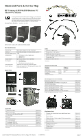
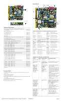
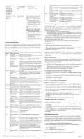
Red Power LED 8 flashes eight times, once every second, followed by a two second pause. Beeps stop after fifth iteration but LEDs continue until problem is solved. System does not power on and LEDs are not flashing. None System board failure or invalid ROM based on bad checksum. 1. Reflash the system ROM with the latest BIOS image. 2. Replace the system board. System unable to power on. Press and hold the power button for less than 4 seconds. If the hard drive LED turns green, the power button is working correctly. Try the following: 1. Check that the voltage selector (some models), located on the rear of the power supply, is set to the appropriate voltage. Proper voltage setting depends on your region. 2. Replace the system board. OR Press and hold the power button for less than 4 seconds. If the hard drive LED does not turn on green then: 1. Check that the unit is plugged into a working AC outlet. 2. Open hood and check that the power button harness is properly connected to the system board. 3. Check that both power supply cables are properly connected to the system board. System Setup and Boot Basic system information regarding system information, setup, power management, hardware, and passwords is maintained in the Setup Utility held in the system ROM. The Setup Utility is accessed by pressing the F10 key when prompted (on screen) to do so during the boot sequence. If the screen prompt opportunity is missed, a restart will be necessary. For more information about Setup Utilities refer to the Service Reference Guide.. Computer Setup Menu Heading Main Option / Description System Time Allows you to set system time. System Date Allows you to set system date. Floppy Diskette A Allows you to set to Disabled, 1.44 MB 3.5", Not Installed. 1st Drive 2nd Drive 3rd Drive 4th Drive Allow you to: view capacity, transfer mode. Also allows you to run HDD self-test for selected channel: SMART status check, SMART short self test, SMART extended self test. System Information Allows you to view CPU type, CPU speed, cache RAM, installed memory, memory banks 1-4, BIOS revision, core version, product name, product number, serial number, UUID, asset tag (press Enter to change). Advanced CPU Type View only. Primary Video Adapter Allows you to select boot display device when more than 2 video options are offered by system: Integrated (Onboard), PCI, PCI-Ex16. PS/2 Mouse Disable/enable/auto detect Internal Speaker Disable/enable. Supervisor Password Allows you to view the supervisor password. User Password Allows you to view the user password. Change Supervisor Password Allows you to change the supervisor password. Power On Password Allows you to disable/enable the Power On Password. Onboard Video Mem- 128MB, 256MB, 512MB ory Size SATA1 Controller Allows you to disabl/enable the SATA1 controller. SATA1 Controller Mode If SATA1 Controller is enabled, allows you to set the mode to: IDE, RAID, AHCI Onboard Audio Allows you to set the onboard audio to: Enabled/disabled/auto Onboard LAN Allows to you disable/enable onboard LAN controller. Onboard LAN Boot Allows you to disable/enable the boot ROM of the ROM onboard LAN chip. USB Ports Allows you to disable/enable USB ports. Hood Sensor Allows you to disable/enable the hood sensoe warning beep. IO Device Configura- Allows you to change the Super IO device resource. tion Power After AC Power Fail- Allows you to select system restart behavior after power ure loss: Stay off, Power on, Auto. XD Disable/enable XD bit. Virtualization Tech- Disable/enable. nology Boot Boot-time Diagnostic Disable/enable POST diagnostic messages display. Screen F9: Boot Menu Allows you to disable/enable Boot Menu. F10: Setup Allows you to disable/enable BIOS Setup Menu. F11: Recovery Allows you to disable/enable HP Backup and Recovery. F12: Boot from LAN Allows you to disable/enable PXE Boot. 1st Boot Device, 2nd Boot Device, 3rd Boot Device, 4th Boot Device Allows you to specify which device groups will boot first, second, third, and fourth or to disable any of the four: Floppy group, CD-ROM group, Hard drive group, Network boot group. MS-DOS drive lettering assignments maybe apply after a non-MS-DOS operating system has started. Floppy Group Boot Specifies boot device priority within removable devices. Priority CD-ROM Boot Prior- Specifies boot device priority within CD/DVD drives. ity Hard Drive Boot Pri- Specifies boot device priority within hard drives. ority Network Group Boot Specifies boot device priority within bootable network Priority devices. Exit Exit Saving Changes Press Enter to exit saving changes. Exit Discarding Changes Press Enter to exit discarding changes. Load Setup Defaults Press Enter to load setup defaults. Discard Changes Press Enter to discard changes. Save Changes Press Enter to save changes. Boot Block Emergency Recovery Mode Boot Block Emergency Recovery Mode permits system recovery in the unlikely event of a ROM flash failure. For example, if a power failure were to occur during a BIOS upgrade, the ROM flash would be incomplete. This would render the system BIOS unusable. The Boot Block is a flash-protected section of the ROM that contains code that checks for a valid system BIOS image when the system is turned on. • If the system BIOS image is valid, the system starts normally. • If the system BIOS image is not valid, a failsafe Boot Block BIOS provides enough support to search removable media for BIOS image files. If an appropriate BIOS image file is found, it is automatically flashed into the ROM. When an invalid system BIOS image is detected, the system power LED will blink red 8 times, one blink every second. Simultaneously, the speaker will beep 8 times. If the portion of the system ROM containing the video option ROM image is not corrupt, Boot Block Emergency Recovery Mode will be displayed on the screen. To recover the system after it enters Boot Block Emergency Recovery Mode, complete the following steps: Boot Block Recovery 1. Remove any bootable media from the computer and turn off power. 2. Insert a USB flash device or CD containing the BIOS image file in the root directory. The media must be formatted using the FAT12, FAT16, or FAT32 file system. 3. Turn on power to the system. 4. The system automatically reprograms the ROM. NOTE: BitLocker prevents Windows Vista from booting when a CD containing the BIOS image file is in an optical drive. If BitLocker is enabled, remove this CD before attempting to boot to Windows Vista. Password Security The Supervisor password is used to authorize the capability to change BIOS Setup options. The User password is used to authorize the capability to change non-critical BIOS Setup options only, such as system date and system time. • To create a user password, a supervisor password should be activated first. • If both Supervisor and User passwords are activated and the correct Supervisor password is entered, all read/write options can be modified. • If both Supervisor and User passwords are activated and the correct User password is entered, all options that cannot be modified must be displayed as read-only. • When a password was not activated, the field displays as "Disabled". Establishing a Supervisor password in Computer Setup 1. Turn on or restart the computer. If you are in Windows, click Start > Shut Down > Restart the Computer. 2. As soon as the computer is turned on, press F10 when the monitor light turns green to enter Computer Setup. Press Enter to bypass the title screen, if necessary. If you do not press F10 when prompted, a restart will be necessary. 3. Select Advanced, and then select Supervisor Password. 4. Before exiting, click File > Save Changes and Exit. Changing a Supervisor or User password If the system is equipped with an embedded security device, refer to the HP ProtectTools Security Manager Guide at http://www.hp.com. 1. Turn on or restart the computer. If you are in Windows, click Start > Shut Down > Restart the Computer. 2. As soon as the computer is turned on, press F10 before the computer boots to the operating system to enter Computer Setup. 3. Select the Advanced menu, select Change supervisor password or Change user password, press Enter to modify the password, and then type the new password. NOTE: Type the new password carefully since the characters do not appear on the screen. 4. Press Enter. The new password will take effect the next time the computer is restarted. Disabling a Supervisor or User password If the system is equipped with an embedded security device, refer to the HP ProtectTools Security Manager Guide at http://www.hp.com. 1. Turn on or restart the computer. If you are in Windows, click Start > Shut Down > Restart the Computer. 2. As soon as the computer is turned on, press F10 when the monitor light turns green to enter Computer Setup. 3. Select the Advanced menu, select Change supervisor password or Change user password, and then press Enter twice to disable the password. 4. Press Enter. HP Insight Diagnostics Diagnostic functions are provided by the Setup Utility (in system ROM) and by HP Insight Diagnostics. The HP Insight Diagnostics utility allows you to view information about the hardware configuration of the computer and perform hardware diagnostic tests on the subsystems of the computer. The utility simplifies the process of effectively identifying, diagnosing, and isolating hardware issues. Insight Diagnostics may be downloaded from the HP Web site using the following procedure: 1. Go to www.hp.com and click the Software & Download driver link. 2. Enter the product number (for example, dc2810) in the text box and press the Enter key. 3. Select the specific product, and then select the OS. 4. Click the Diagnostics link. 5. Select HP Insight Diagnostics Offline Edition. 6. Click Download. NOTE: The download includes instructions on how to create a bootable CD. dx2810/dx2818 Illustrated Parts & Service Map, MT chassis 516944-003 page 3
-
 1
1 -
 2
2 -
 3
3
 |
 |