HP dx7518 Illustrated Parts & Service Map: HP Compaq dx7510/dx7518 Busines - Page 3
System Setup and Boot, Computer Setup Menu - bios
 |
View all HP dx7518 manuals
Add to My Manuals
Save this manual to your list of manuals |
Page 3 highlights
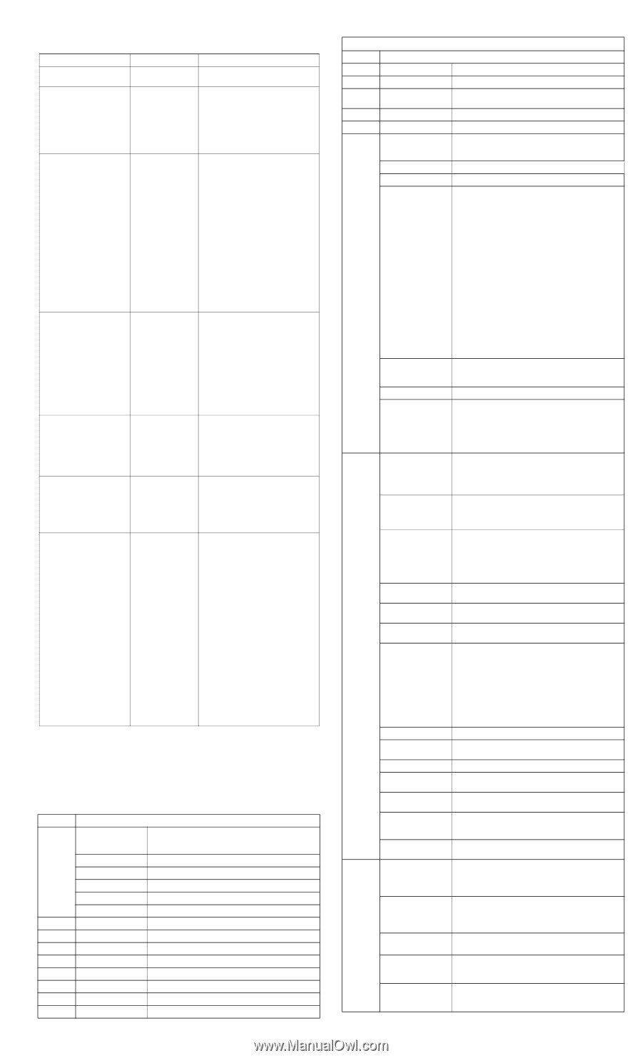
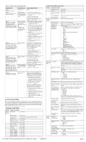
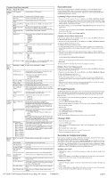
POST Front Panel LEDs and Audible Codes Beeps/Activity Possible Cause Recommended Action 0 Beeps Green Power LED On Computer on None 0 Beeps Green Power LED flashes every two seconds Computer in Suspend to RAM mode (some models only) or normal Suspend mode. For systems with a graphics card: 1. Reseat the graphics card. Power on the system. 2. Replace the graphics card. 3. Replace the system board. For systems with integrated graphics, replace the system board. 2 Beeps CPU fan is weak (RPM < 1000) or not turning. A warning message is displayed along with a series of long beeps for five seconds, then the system shuts down Processor thermal protection activated: A fan may be blocked or not turning. OR The heatsink/fan assembly is not properly attached to the processor. 1. Ensure that the computer air vents are not blocked and the processor cooling fan is running. 2. Open hood, press power button, and see if the processor fan spins. If the processor fan is not spinning, make sure the fan's cable is plugged onto the system board header. Ensure the fan is fully/properly seated and installed. 3. If fan is plugged in and seated properly, but is not spinning, then replace processor fan. 4. Reseat processor heatsink and verify that the fan assembly is properly attached. 5. Contact an authorized reseller or service provider. 5 Beeps Red Power LED flashes five times, once every second, followed by a two second pause. Beeps stop after fifth iteration but LEDs continue until problem is solved Pre-video memory error. CAUTION: To avoid damage to the DIMMs or the system board, you must unplug the computer power cord before attempting to reseat, install, or remove a DIMM module. 1. Reseat DIMMs. 2. Replace DIMMs one at a time to isolate the faulty module. 3. Replace third-party memory with HP memory. 4. Replace the system board. 6 Beeps Red Power LED flashes six times, once every second, followed by a two second pause. Beeps stop after fifth iteration but LEDs continue until problem is solved Pre-video graphics error. For systems with a graphics card: 1. Reseat the graphics card. 2. Replace the graphics card. 3. Replace the system board. For systems with integrated graphics, replace the system board. 8 Beeps Red Power LED flashes eight times, once every second, followed by a two second pause. Beeps stop after fifth iteration but LEDs continue until problem is solved System board failure or invalid ROM based on bad checksum. 1. Reflash the system ROM with the latest BIOS image. 2. Replace the system board. 0 Beeps System does not power on and LEDs are not flashing System unable to power on. Press and hold the power button for less than 4 seconds. If the hard drive LED turns green, the power button is working correctly. Try the following: 1. Check that the voltage selector (some models), located on the rear of the power supply, is set to the appropriate voltage. Proper voltage setting depends on your region. 2. Replace the system board. OR Press and hold the power button for less than 4 seconds. If the hard drive LED does not turn on green then: 1. Check that the unit is plugged into a working AC outlet. 2. Open hood and check that the power button harness is properly connected to the system board. 3. Check that both power supply cables are properly connected to the system board. System Setup and Boot Basic system information regarding system information, setup, power management, hardware, and passwords is maintained in the Setup Utility held in the system ROM. The Setup Utility is accessed by pressing the F10 key when prompted (on screen) to do so during the boot sequence. If the screen prompt opportunity is missed, a restart is necessary. For more information about Setup Utilities refer to the Service Reference Guide.. Computer Setup Menu Heading System Information Option / Description System S/N (view only) Product Name Ownership Tag BIOS Version BIOS Release Date System Chipset Type Processor Type Processor Speed CPU ID Cache Size Memory DIMM1 Memory DIMM2 Memory DIMM3 Memory DIMM4 (view only) Enter ownership tag assigned by the owner. (view only) (view only) (view only) (view only) (view only) (view only) (view only) (view only) (view only) (view only) (view only) Computer Setup Menu (continued) Heading Option / Description DDR Memory Size (view only) UUID (view only) Chassis Serial Num- (view only) ber Asset Tag Number Enter asset tag number assigned by the company. Integrated MAC (view only) Standard Date (mm:dd:yy: CMOS Features Allows you to set system date. Time (hh:mm:ss) Allows you to set system time. Floppy Drive A Allows you to set Drive A of None or 1.44M, 3.5 inch. SATA Port 0 SATA Port 1 SATA Port 2 SATA Port 3 For each, allows you to: • detect HDD size and head on selected channel • set extended drive on selected channel to: - None - Auto - Manual • set access mode on selected channel to: - CHS - LBA - Large - Auto • view: - Capacity - Cylinder - Head - Precomp - Landing Zone - Sector • SMART Support - SMART Status Check - SMART Short Self-Test - SMART Extended Self-Test SATA Mode Allows you to set the SATA mode to: • IDE • AHCI Legacy Mode Support Disables/enables legacy mode support. Halt On Allows you to set POST error behavior to: • All Errors • No Errors • All but Keyboard • All but Diskette • All but Diskette/Keyboard Advanced F11 Prompt BIOS Features Setting this feature to displayed will display the text F11 = Recovery during POST. Hiding this feature prevents the text from being displayed. However, pressing F11 will still attempt to boot to the HP Backup and Recovery partition. Quick Power On Self Test Disables/enables the system to skip certain tests while booting. Enabling this feature decreases the time required to boot the system. POST Delay Time Allows you to set a POST delay time to: • None • 5 Seconds • 10 Seconds • 15 Seconds • 20 Seconds Hard Drive Boot Pri- Specifies boot device priority within hard drives. ority CD-ROM Boot Prior- Specifies boot device priority within CD/DVD drives. ity Network Group Boot Specifies boot device priority within bootable network Priority devices. First Boot Device Second Boot Device Third Boot Device Fourth Boot Device Allows you to specify which device groups will boot first, second, third, and fourth or to disable any of the four: • Removable • Hard Disk • CDROM • Network • Disabled NOTE: MS-DOS drive lettering assignments maybe apply after a non-MS-DOS operating system has started. Boot Other Device Disables/enables boot other device. Load Boot Menu Selectable Disables/enables boot menu selectable. APIC Mode Disables/enables the Advanced-PIC mode. System Keyboard Allows you to set the system keyboard to Absent or Present. Boot Up NumLock Allows you to set the default NumLock status to off or Status on. Security Option Allows you to set the security option to Setup or System so that the password is required every time the system boots or only when entering Computer Setup. HDD S.M.A.R.T. Capability Disables/enables hard drive S.M.A.R.T. capability. Advanced On-Chip Frame Chipset Buffer Size Features (VGA Setting) Select the On-Chip Frame Buffer Size to: • 32MB • 64MB • 128MB PEG/Onchip VGA Control Allows you to set VGA control to: • Onchip VGA • PEG port • Auto DVMT Mode (VGA Setting) Disables/enables DVMT mode. DVMT/FIXED Mem- Allows you to set memory size to: ory Size • 128MB (VGA Setting) • 256MB Init Display First (VGA Setting) Allows you to select the primary display device: • PCI Slot • Onboard dx7510/dx7518 Illustrated Parts & Service Map, MT chassis 516948-001 page 3
-
 1
1 -
 2
2 -
 3
3 -
 4
4
 |
 |