HP t5550 HP t5550/t5565/t5570 Thin Clients Hardware Reference Guide
HP t5550 - Thin Client Manual
 |
View all HP t5550 manuals
Add to My Manuals
Save this manual to your list of manuals |
HP t5550 manual content summary:
- HP t5550 | HP t5550/t5565/t5570 Thin Clients Hardware Reference Guide - Page 1
Hardware Reference Guide HP t5550/t5565/t5570 Thin Clients - HP t5550 | HP t5550/t5565/t5570 Thin Clients Hardware Reference Guide - Page 2
Microsoft and Windows are trademarks of Microsoft Corporation in the U.S. and other countries. The only warranties for HP products and services are set of Hewlett-Packard Company. Hardware Reference Guide HP t5550/t5565/t5570 Thin Clients First Edition (September 2010) Document Part Number: 621018 - HP t5550 | HP t5550/t5565/t5570 Thin Clients Hardware Reference Guide - Page 3
About This Book WARNING! Text set off in this manner indicates that failure to follow directions could result in bodily harm or loss of life. CAUTION: Text set off in this manner indicates that failure to follow directions could result in damage to equipment or loss of information. NOTE: Text set - HP t5550 | HP t5550/t5565/t5570 Thin Clients Hardware Reference Guide - Page 4
iv About This Book ENWW - HP t5550 | HP t5550/t5565/t5570 Thin Clients Hardware Reference Guide - Page 5
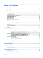
USB Device 15 Removing and Replacing the Battery 16 Installing a Secondary Flash Memory Module 18 External Drives ...19 Appendix A Specifications ...20 Appendix B Security Provisions ...22 Securing the Thin Client ...22 Appendix C Mounting the Thin Client ...23 HP Quick Release ...23 Supported - HP t5550 | HP t5550/t5565/t5570 Thin Clients Hardware Reference Guide - Page 6
28 Routine Thin Client Care ...28 Supported Orientations ...29 Non-supported Orientation ...30 Appendix E Electrostatic Discharge ...31 Preventing Electrostatic Damage ...31 Grounding Methods ...31 Appendix F Shipping Information ...32 Shipping Preparation ...32 Important Service Repair Information - HP t5550 | HP t5550/t5565/t5570 Thin Clients Hardware Reference Guide - Page 7
sections describe the features of the thin client. For a complete list of the hardware and software installed on a specific model, visit http://www.hp.com and search for your specific thin client model. The following features are common to all HP thin clients: ● no hard drives or diskette drives - HP t5550 | HP t5550/t5565/t5570 Thin Clients Hardware Reference Guide - Page 8
) connectors (2) Top Components For more information, http://www.hp.com and search for your specific thin client model to find the model-specific QuickSpecs. The secure USB compartment allows you to use two USB devices in a secured location. Figure 1-2 Top components, external view (1) Cable lock - HP t5550 | HP t5550/t5565/t5570 Thin Clients Hardware Reference Guide - Page 9
Panel Components For more information, http://www.hp.com and search for your specific thin client model to find the model-specific QuickSpecs. Figure 1-4 Rear panel components (1) Wireless antenna* (7) Universal serial bus (USB) connectors (2) (2) Ethernet RJ-45 connector (8) DVI-D connector - HP t5550 | HP t5550/t5565/t5570 Thin Clients Hardware Reference Guide - Page 10
the Antenna (Wireless Models) ▲ Screw the antenna in place on the rear of the thin client. Figure 1-5 Installing the antenna CAUTION: To prevent damage to the antenna mounting, do not overtighten the antenna. Installing the Rubber Feet You may want to use your thin client in a horizontal orientation - HP t5550 | HP t5550/t5565/t5570 Thin Clients Hardware Reference Guide - Page 11
the feet with their holes and press them in securely. Figure 1-6 Installing the rubber feet Installing the Stand If you want to use the thin client in a vertical orientation, you will need to install the stand for stability. To install the stand: 1. Turn unit upside down. 2. Position the stand with - HP t5550 | HP t5550/t5565/t5570 Thin Clients Hardware Reference Guide - Page 12
Removing the Stand To remove the stand: 1. Turn unit upside down. 2. Press down on the tab (1), and then slide the stand toward the rear of the unit and pull it up to remove it from the unit (2). Figure 1-8 Removing the stand Using the Power Cord Retention Slot To prevent accidental disconnection, - HP t5550 | HP t5550/t5565/t5570 Thin Clients Hardware Reference Guide - Page 13
Down. Hold Ctrl and Alt while pressing Delete to restart the thin client. 1Available in select geographic regions. 2For local sessions, applies only to thin clients running Windows Embedded Standard. For full-screen remote Windows sessions, applies to all thin clients. ENWW Using the Keyboard 7 - HP t5550 | HP t5550/t5565/t5570 Thin Clients Hardware Reference Guide - Page 14
or folder. Search for computers. Minimize all windows. Undo minimize all. Display the System Properties dialog box. Open the Run dialog box. Additional Function Keys The following key combinations also work on all thin clients regardless of operating system: Alt + Esc Alt + Tab Alt + Shift + Tab - HP t5550 | HP t5550/t5565/t5570 Thin Clients Hardware Reference Guide - Page 15
Serial Number Location Every thin client includes a unique serial number located as shown in the following illustration. Have this number available when contacting HP customer service for assistance. Figure 1-11 Serial number location ENWW Serial Number Location 9 - HP t5550 | HP t5550/t5565/t5570 Thin Clients Hardware Reference Guide - Page 16
2 Hardware Changes General Hardware Installation Sequence To ensure the proper installation thin client hardware components: 1. Back up any data, if necessary. 2. If the thin client is powered on: a. Turn off the computer properly through the operating system, then turn off any external devices. b. - HP t5550 | HP t5550/t5565/t5570 Thin Clients Hardware Reference Guide - Page 17
drivers. NOTE: You can download select hardware drivers from HP. Go to http://www.hp.com and search for your specific thin client model. 13. Reconfigure the thin client, if necessary. Removing and Replacing the Secure USB Compartment Cover The secure USB compartment allows you to install two USB - HP t5550 | HP t5550/t5565/t5570 Thin Clients Hardware Reference Guide - Page 18
the chassis (2). 3. Replace the screw (3). Figure 2-2 Replacing the secure compartment cover Removing and Replacing the Side Access Panel and Metal Side Cover Removing the Side Access Panel and Metal Side Cover WARNING! Before removing the side access panel, ensure that the thin client is turned - HP t5550 | HP t5550/t5565/t5570 Thin Clients Hardware Reference Guide - Page 19
compartment cover (1). For more information, see Removing the Secure USB Compartment Cover on page 11. 2. Remove the stand, if it is installed (2). See Removing the Stand on page 6 for more 2-4 Removing the metal side cover ENWW Removing and Replacing the Side Access Panel and Metal Side Cover 13 - HP t5550 | HP t5550/t5565/t5570 Thin Clients Hardware Reference Guide - Page 20
the top of the unit (1). 2. Slide the access panel toward the bottom of the unit until it is flush with the bottom of the chassis (2). 3. Replace the secure compartment cover. For more information, see Replacing the Secure USB Compartment Cover on page 12. 14 Chapter 2 Hardware Changes ENWW - HP t5550 | HP t5550/t5565/t5570 Thin Clients Hardware Reference Guide - Page 21
can be installed on the thin client: ● Installing the USB Device on page 15 ● Removing and Replacing the Battery on page 16 ● Installing a Secondary Flash Memory Module on page 18 ● External Drives on page 19 Installing the USB Device Before beginning the replacement process, review General Hardware - HP t5550 | HP t5550/t5565/t5570 Thin Clients Hardware Reference Guide - Page 22
the Battery Before beginning the replacement process, review General Hardware Installation Sequence on page 10 for procedures you should follow before and after installing or replacing hardware. WARNING! Before removing the side access panel, ensure that the thin client is turned off and the - HP t5550 | HP t5550/t5565/t5570 Thin Clients Hardware Reference Guide - Page 23
Disposal Act, to indicate the recovery marks on the batteries used in sales, giveaways, or promotions. Contact a qualified Taiwanese recycler for proper battery disposal. ENWW Installing Thin Client Options 17 - HP t5550 | HP t5550/t5565/t5570 Thin Clients Hardware Reference Guide - Page 24
process, review General Hardware Installation Sequence on page 10 for procedures you should follow before and after installing or replacing hardware. WARNING! You must remove the right side panel to access the system board. Before removing the side access panel, ensure that the thin client is - HP t5550 | HP t5550/t5565/t5570 Thin Clients Hardware Reference Guide - Page 25
http://www.hp.com and search for your specific thin client model, or refer to the instructions that accompany the option. For more information about available options, visit the HP Web sitehttp://www.hp.com and search for your specific thin client model. ENWW Installing Thin Client Options 19 - HP t5550 | HP t5550/t5565/t5570 Thin Clients Hardware Reference Guide - Page 26
A Specifications Table A-1 HP t5550/t5565/t5570 Thin Client Dimensions Width Height (without stand) Height (with be limited by the type and number of options installed. ** The operating temperature range when the thin client is attached to a flat panel using the HP Quick Release is 50° to 95° F ( - HP t5550 | HP t5550/t5565/t5570 Thin Clients Hardware Reference Guide - Page 27
Table A-1 HP t5550/t5565/t5570 Thin Client (continued) Rated Output Current (maximum) 3.42 A Output Voltage +19 V DC 3.42 A +19 V DC ENWW 21 - HP t5550 | HP t5550/t5565/t5570 Thin Clients Hardware Reference Guide - Page 28
www.hp.com and search for your specific thin client model. 1. Locate the cable lock slot on the back panel. 2. Insert the cable lock into the slot, and then use the key to lock it. Figure B-1 Securing the thin client You may also secure your USB mouse and keyboard or other USB devices by installing - HP t5550 | HP t5550/t5565/t5570 Thin Clients Hardware Reference Guide - Page 29
to the VESA-standard mounting points, allowing you to mount the thin client in a variety of orientations. NOTE: When mounting to a thin client, use the 15 mm screws supplied with the HP Quick Release. Figure C-1 HP Quick Release To use the HP Quick Release: 1. Using four 15 mm screws included in the - HP t5550 | HP t5550/t5565/t5570 Thin Clients Hardware Reference Guide - Page 30
side of the mounting device (2) on the device on which you want to mount the thin client. An audible 'click' indicates a secure connection. Figure C-4 Connecting the thin client NOTE: When attached, the HP Quick Release automatically locks in position. You only need to slide the lever to one side - HP t5550 | HP t5550/t5565/t5570 Thin Clients Hardware Reference Guide - Page 31
Supported Mounting Options The following illustrations demonstrate some of the supported and not supported mounting options for the mounting bracket. Figure C-5 Thin client mounted with flat panel on wall Figure C-6 Thin client mounted on back of monitor stand ENWW HP Quick Release 25 - HP t5550 | HP t5550/t5565/t5570 Thin Clients Hardware Reference Guide - Page 32
Figure C-7 Thin client mounted on wall Figure C-8 Thin client mounted under desk 26 Appendix C Mounting the Thin Client ENWW - HP t5550 | HP t5550/t5565/t5570 Thin Clients Hardware Reference Guide - Page 33
a thin client in an non-supported manner could result in failure of the HP Quick Release and damage to the thin client and/or other equipment. Do not mount the thin client on a flat panel monitor stand, between the panel and the stand. Figure C-9 Unsupported mounting position-thin client between - HP t5550 | HP t5550/t5565/t5570 Thin Clients Hardware Reference Guide - Page 34
heat and cold. For information about the recommended temperature and humidity ranges for the thin client, see Specifications on page 20. ● Keep liquids away from the thin client and keyboard. ● Turn off the thin client and wipe the exterior with a soft, damp cloth as needed. Using cleaning products - HP t5550 | HP t5550/t5565/t5570 Thin Clients Hardware Reference Guide - Page 35
Supported Orientations HP supports the following orientations for the thin client. CAUTION: You must adhere to HP-supported orientations to ensure your thin clients function properly. Figure D-1 Vertical orientation using the supplied stand Figure D-2 Horizontal orientation on rubber feet Figure - HP t5550 | HP t5550/t5565/t5570 Thin Clients Hardware Reference Guide - Page 36
Non-supported Orientation HP does not support the following orientation for the thin client. CAUTION: Non-supported placement of thin clients could result in operation failure and/or damage to the devices. CAUTION: Thin clients require proper ventilation to maintain operating temperature. Do not - HP t5550 | HP t5550/t5565/t5570 Thin Clients Hardware Reference Guide - Page 37
may damage system boards or installing electrostatic-sensitive parts: ● Use a wrist strap connected by a ground cord to a grounded Thin Client HP authorized dealer, reseller, or service provider. NOTE: For more information about static electricity, contact an HP authorized dealer, reseller, or service - HP t5550 | HP t5550/t5565/t5570 Thin Clients Hardware Reference Guide - Page 38
. NOTE: For environmental nonoperating ranges, see Specifications on page 20 Important Service Repair Information In all cases, remove and safeguard all external options before returning the thin client to HP for repair or exchange. In countries that support customer mail-in repair by returning the - HP t5550 | HP t5550/t5565/t5570 Thin Clients Hardware Reference Guide - Page 39
memory module 18 stand 5 thin client onto HP Quick Release 23 USB devices 1, 11, 15 K keyboard function keys 8 layout 7 Windows logo key 8 L line-out audio location 3 lock, cable, slot location 2 M memory module, installing 18 metal side cover removing 12 replacing 14 microphone connector location - HP t5550 | HP t5550/t5565/t5570 Thin Clients Hardware Reference Guide - Page 40
20 thin client 20 weight 20 stand installing 5 removing 6 supported mounting options 25 supported orientations horizontal 29 under monitor stand 29 vertical 29 T temperature specifications 20 top components 2 U unsupported mounting option 27 USB compartment security 22 USB devices, installing 1, 11
-
 1
1 -
 2
2 -
 3
3 -
 4
4 -
 5
5 -
 6
6 -
 7
7 -
8
-
9
-
10
-
11
-
12
-
13
-
14
-
15
-
16
-
17
-
18
-
19
-
20
-
21
-
22
-
23
-
24
-
25
-
26
-
27
-
28
-
29
-
30
-
31
-
32
-
33
-
34
-
35
-
36
-
37
-
38
-
39
-
40
 |
 |

Hardware Reference Guide
HP t5550/t5565/t5570 Thin Clients