HP t5565 HP t5550/t5565/t5570 Thin Clients Hardware Reference Guide - Page 30
C-3, CAUTION, Mounting the Thin Client
 |
View all HP t5565 manuals
Add to My Manuals
Save this manual to your list of manuals |
Page 30 highlights
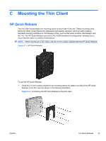
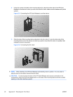
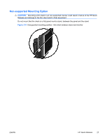
2. Using four screws included in the mounting device kit, attach the other side of the HP Quick Release to the device to which you will mount the thin client. Make sure the release lever points upward. Figure C-3 Connecting the HP Quick Release to another device 3. Slide the side of the mounting device attached to the thin client (1) over the other side of the mounting device (2) on the device on which you want to mount the thin client. An audible 'click' indicates a secure connection. Figure C-4 Connecting the thin client NOTE: When attached, the HP Quick Release automatically locks in position. You only need to slide the lever to one side to remove the thin client. CAUTION: To ensure proper function of the HP Quick Release and a secure connection of all components, make sure both the release lever on one side of the mounting device and the rounded opening on the other side face upward. 24 Appendix C Mounting the Thin Client ENWW
-
 1
1 -
2
-
3
-
4
-
5
-
6
-
7
-
8
-
9
-
10
-
11
-
12
-
13
-
14
-
15
-
16
-
17
-
18
-
19
-
20
-
21
-
22
-
23
-
24
-
 25
25 -
 26
26 -
 27
27 -
 28
28 -
 29
29 -
 30
30 -
 31
31 -
 32
32 -
 33
33 -
 34
34 -
 35
35 -
36
-
37
-
38
-
39
-
40
 |
 |
