HP t5740e HP t5740/t5745 Thin Clients Hardware Reference Guide - Page 17
Hardware Changes, General Hardware Installation Sequence - flash memory
 |
View all HP t5740e manuals
Add to My Manuals
Save this manual to your list of manuals |
Page 17 highlights
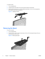
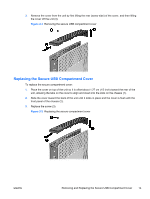
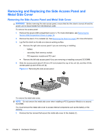
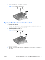
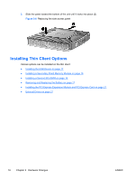
2 Hardware Changes General Hardware Installation Sequence To ensure the proper installation thin client hardware components: 1. Back up any data, if necessary. 2. If the thin client is powered on: a. Turn the unit and any other attached devices off. b. Disconnect the power cord from the wall outlet. c. Disconnect any external devices or cables, such as an antenna or cable lock. WARNING! To reduce the risk of personal injury from electrical shock and/or hot surfaces, be sure to disconnect the power cord from the wall outlet and allow the internal system components to cool before touching. WARNING! To reduce the risk of electrical shock, fire, or damage to the equipment, do not plug telecommunications or telephone connectors into the network interface controller (NIC) receptacles. CAUTION: Static electricity can damage the electronic components of the thin client or optional equipment. Before beginning these procedures, ensure that you are discharged of static electricity by briefly touching a grounded metal object. See Electrostatic Discharge on page 32 for more information. 3. Remove the secure USB compartment cover. See Removing and Replacing the Secure USB Compartment Cover on page 12 for more information. 4. Remove the stand, if it is installed. See Removing the Stand on page 6 for more information. 5. Remove the side access panel and metal side cover. See Removing and Replacing the Side Access Panel and Metal Side Cover on page 14 for more information. 6. Remove any hardware that you will replace. 7. Install or replace equipment. For removal and replacement procedures, see the following sections: ● Installing the USB Device on page 17 ● Installing the PCI Express Expansion Module and PCI Express Card on page 21 ● Removing and Replacing the Battery on page 17 ● Installing a Secondary Flash Memory Module on page 18 ● Installing a Second SO-DIMM on page 19 NOTE: Option kits include more detailed installation instructions. 8. Replace the side access panel and metal side cover. See Removing and Replacing the Side Access Panel and Metal Side Cover on page 14 for more information. ENWW General Hardware Installation Sequence 11
-
 1
1 -
2
-
3
-
4
-
5
-
6
-
7
-
8
-
9
-
10
-
11
-
 12
12 -
 13
13 -
 14
14 -
 15
15 -
 16
16 -
 17
17 -
 18
18 -
 19
19 -
 20
20 -
 21
21 -
 22
22 -
23
-
24
-
25
-
26
-
27
-
28
-
29
-
30
-
31
-
32
-
33
-
34
-
35
-
36
-
37
-
38
-
39
-
40
-
41
 |
 |