Hitachi 32HDL52 Owners Guide - Page 18
Monitor output table, a Normal mode
 |
View all Hitachi 32HDL52 manuals
Add to My Manuals
Save this manual to your list of manuals |
Page 18 highlights
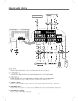
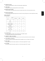
English ⑫ SUBWOOFER Output Connect this SUB WOOFER OUT output to the external audio component input. ⑬ AUDIO Output These jacks provide fixed audio signal which are used for recording. ⑭ MONITOR Output (S VIDEO) This jack provides S video signal which are used for recording. (Please refer to monitor output table as below) ⑮ MONITOR Output (VIDEO) This jack provides video and audio signals which are used for recording. (Please refer to monitor output table as below) Monitor output table: (a) Normal mode: Input Output DTV NTSC VIDEO1/ VIDEO2 VIDEO3/ VIDEO4 (VIDEO) VIDEO3/ VIDEO4 (S-VIDEO) ANALOG RGB DVI S-VIDEO ○ × × × ○ × × VIDEO × × × AUDIO ○ × × (b) For POP/PIP mode: The monitor output is according to user's selected source, the speaker's position. The output table should be the same with the above table. ⑯ L/MONO /R (VIDEO 1 and VIDEO 2) Connect audio of external devices.(if you have mono sound, insert the audio cable into the left (L) audio jack). ⑰ Y-PBPR (VIDEO 1 and VIDEO 2) Provide Y-PBPR jacks for connecting equipment with this capability, such as a DVD player or Set Top Box ⑱ NTSC TUNER RF input that connects to the antenna, cable box, or CATV cable. Support NTSC TV system. ⑲ DTV TUNER RF input that connects to the antenna, cable box, or CATV cable. Support ATSC TV system. 17
-
 1
1 -
2
-
3
-
4
-
5
-
6
-
7
-
8
-
9
-
10
-
11
-
12
-
 13
13 -
 14
14 -
 15
15 -
 16
16 -
 17
17 -
 18
18 -
 19
19 -
 20
20 -
 21
21 -
 22
22 -
 23
23 -
24
-
25
-
26
-
27
-
28
-
29
-
30
-
31
-
32
-
33
-
34
-
35
-
36
-
37
-
38
-
39
-
40
-
41
-
42
-
43
-
44
-
45
-
46
-
47
-
48
-
49
-
50
-
51
-
52
 |
 |
